E-44-
1067
POSITIONER TYPE 1067APPENDIX
A3 : OPTION BOARD "4-20 mA ANALOG POSITION INDICATION"
(IDENT. 427193G): MOUNTING AND CONNECTION
The positioner must be equipped with the software version F, or higher. Check it in the
main menu, option END: it is displayed at the right-hand side of the screen.
Technical characteristics of the Option output of the positioner
- Output signal for the current value : 4-20 mA
- External working resistance / Input resistance of a connected device : 0-560 Ohms
- Output error rate : < 0,05 %
- Potential free output ; electrically separated from the position electronics.
Mounting
- Disconnect the positioner from the voltage supply
- Unscrew the 4 screws of the positioner cover and open the cover
- Remove the 2 red jumpers from the motherboard
- Insert the optional board onto the motherboard (see figure below)
Make sure the pins correctly slide into the motherboard.
- Pass the cables through one of the 2 PG9 cable glands, dismantle them over 6 mm and
connect them to the connection block according to the connection schematic (terminals I/O3
and I/O4)
- Close the cover and tighten the 4 screws, making sure neither the cables nor the wires are
wedged in.
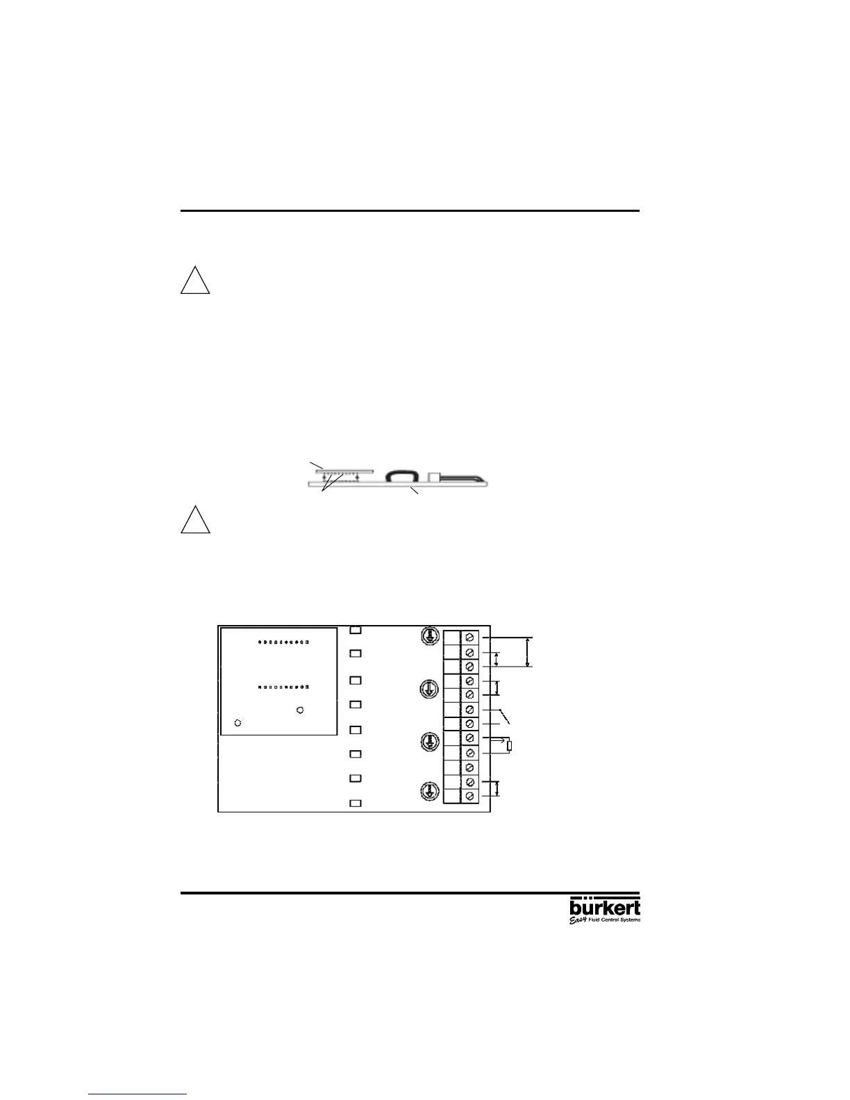
Connection diagram
Configuration
- Configurate the positioner as described in chapter 4.5.
- Activate the analog position indication by choosing the ANALOG option of the OUTPUT
function
Analog Option board
Motherboard
pins
!
!
I1
U1
GND1
I2
GND2
I/O1
I/O2
I/O3
I/O4
PE
+24 V
-
0-10 V
0/4-20 mA
4-20 mA
I
L
= 4-20 mA
R
L
= 0-560 Ohm
24 V DC Supply Voltage
Analog Option board
Motherboard
+
-