E-46-
1067
POSITIONER TYPE 1067APPENDIX
Connection
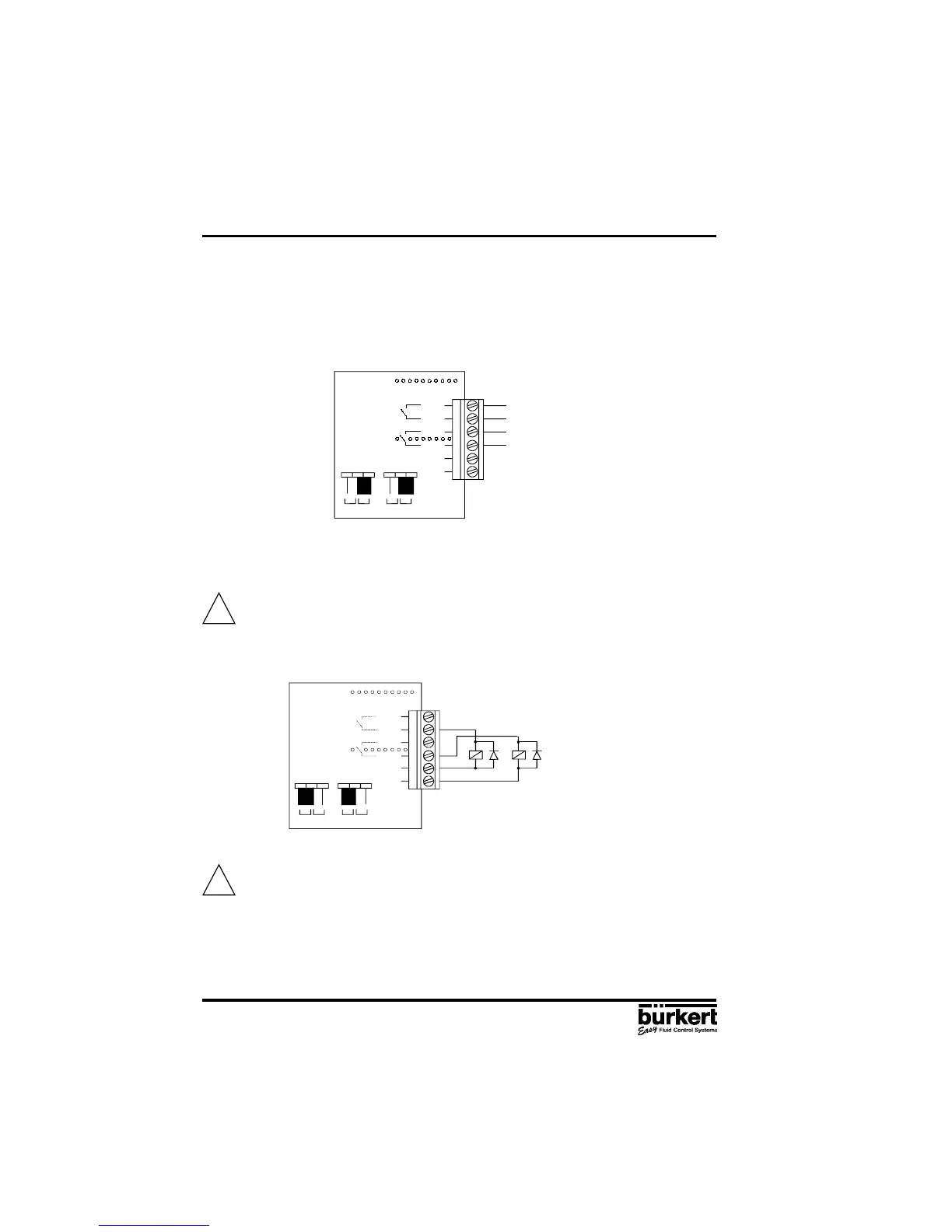
1) As potential free contacts
- connect the cables to the O5 and O6 or O7 and O8 terminals according to the connection
schematic
- place the jumper on the "REL" position (see figure below)
2) For connecting receivers to the outputs O6 and O8 (operating voltage of 24 V DC)
- connect the cables to the terminals O6 and O8 and to GND3 and GND4 according to the connection
schematic below.
For inductive receivers, use the recovery diode.
- place the jumper on the "U
out
" position (see figure below)
Short-circuit hazard : before closing the device, make sure the screws of the
connection block are tightend.
- Close the cover and tighten the 4 screws, making sure the cables are not wedged in.
Configuration
- Configurate the positioner as described in chapter 4.5.
- Activate the binary position indication or the Booster function by choosing either the BINARY
or the BOOST option in the OUTPUT function.
!
!
O5
O6+
O7
O8+
GND3
GND4
U
out
Rel
U
out
Rel
O5
O6+
O7
O8+
GND3
GND4
U
out
Rel
U
out
Rel