7.6.2. Wiring a "trace" chlorine sensor with
4-pin connector
NOTE
Risk of damage to the sensor due to the power supply.
▶ Make sure the power supply is in the range 9...30 V DC.
The "trace" chlorine sensor (order code 565164) has a 0...+2 V
output.
Table 1 : Signal assignment of the cable with order code 565385
(ordered separately)
Wire colour Signal
Green Ground
(negative voltage signal)
Yellow 0...2 V signal
(positive voltage signal)
White Positive power supply
Brown Negative power supply
→ Use a cable with a max. length of 30 m.
→ Connect the sensor with the remote controller type 8619.
Refer to the Operating Instructions of the related remote
controller.
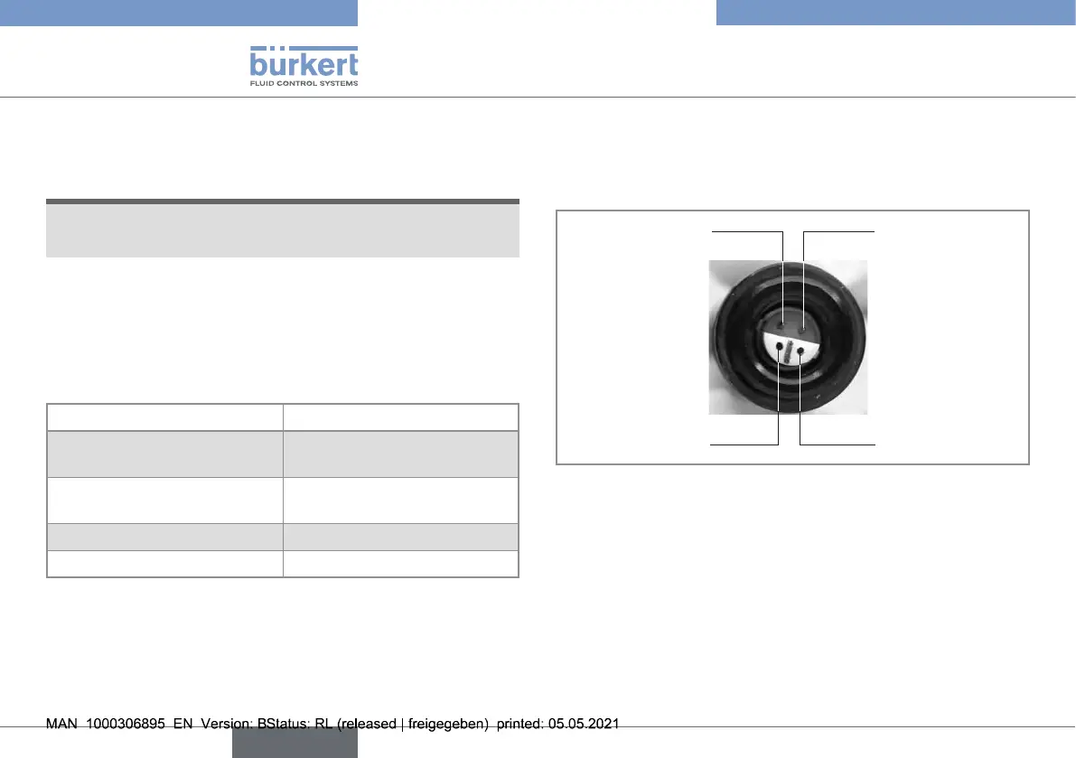
negative voltage signal
negative power supply
positive power supply
positive voltage signal
Fig. 5 : Pin assignment of the "trace" chlorine sensor with order
code 565164
7.6.3. Wiring a sensor with cable plug PG7
The sensor with cable plug PG7 has a 4...20 mA current output.
The sensor is electrically fed by the remote controller type 8619 the
sensor is connected to.
20
Installation and wiring
Type 8232
english