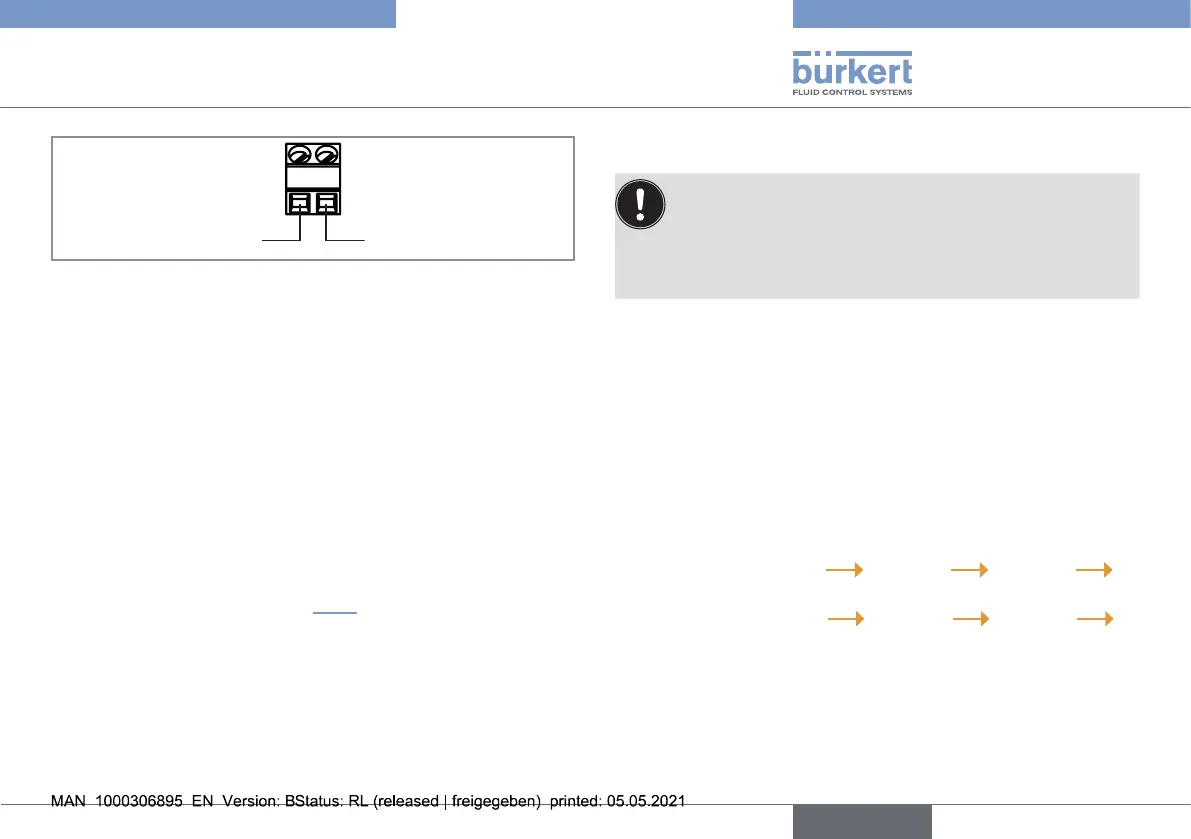
Positive power supply Negative power supply
- +
Fig. 6 : Terminal assignment of a sensor with cable plug PG7
→ Use cables with the following features:
• not shielded;
• 4 mm in diameter;
• 5 m max. length;
• wires with 0,25 mm
2
in section.
1. Loosen the cap for the terminal strip from the shaft.
2. Loosen the nut of the cable gland.
3. Insert the cable through the nut then through the cable gland
then through the cap for the terminal strip.
4. Wire the sensor according to Fig. 6 and according to the
remote controller type 8619. Refer to the related Operating
Instructions.
5. Pull the cable so that it does not block the inside of the cap for
the terminal strip.
6. Tighten by hand the cap for the terminal strip.
7. Tighten by hand the nut of the cable gland.
8. COMMISSIONING
▶ If there are bubbles on the membrane, increase the flow
rate temporarily to eliminate them.
▶ Respect the Run-in time.
▶ Calibration has to be done after the run-in time for ensur-
ing a proper reading (sensor needs to be powered!).
8.1. Commissioning of the chlorine
sensor with order codes 568524
and 568523
Before commissioning:
1. Open the measuring water outlet of the analytical measurement
chamber.
2. Slowly open the measuring water supply. A constant low flow
rate in a range of 15...30 l/h is recommended.
3. In the Operating Instructions of the remote controller type 8619:
- a) Menu "Parameters"
Mx: Inputs AI1 or AI2
Mode = Current
- b) Menu "Parameters"
Mx: Inputs AI1 or AI2
Range = 4...20 mA
- c) Enter for 4 mA: 0 and for 20 mA: 20.
21
Commissioning
Type 8232
english