Operating Instructions No. 803 925 29
english
➔
Screw the (brass) guide piece into the cover of the valve drive by hand,
without fully tightening it at the moment.
➔
Tighten the SW 27 (brass) guide piece with a torque of 8.0 Nm.
➔
Tighten the switch spindle onto the piston rod of the drive. A slot is provided
on the side of the spindle for this purpose (torque = 1.0 Nm).
➔
Push the two supplied switching cams onto the switch spindle (Diameter 5
mm). Push the first cam right up to the guide piece (brass part) and the
second cam only a little beyond the upper end of the switch spindle
(approx. 5 to max. 10 mm).
➔
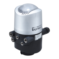
Fit the Top
Control
housing. The switch spindle must be inserted from above
into the central bore of the Top
Control
housing, which can be seen through
the see-through cover.
When installing units with mechanical limit switches, ensure that the
latter will not be damaged by the switch spindle, for example, by
being inserted at an angle!
Also ensure that the two threaded SW2 pins used to secure the
Top
Control
do not protrude into the fixing opening on the lower side
of the housing. The tips of the threaded pins could damage the O-
ring on the brass guide component.
Force has to be used in fitting the Top
Control
housing, as the adjustment of
the ”upper” switching cam takes place during the installation of the
TopControl (see ”Adjusting the switch points of the limit switches”).
➔
Press the Top
Control
housing completely down to the drive and align it in
the desired position by turning. Note that it is preferable to have the
pneumatic connections of the Top
Control
and those of the valve drive
vertically above each other, as longer hoses than those provided as
accessories would be required for any other position.
➔
Screw the hose connections onto the Top
Control
and the valve drive.
➔
Set up the pneumatic connection between the Top
Control
and the valve
drive using the hoses provided in the accessory set.
➔
Then secure the Top
Control
housing onto the valve drive by moderately
tightening the two threaded rods using an SW2 Allen key (max. 0.4 Nm).
(See Fig. 2).



 To Next Page