32
Top
Control
ON/OFF
english
3.4 Fluid connection of the Top
Control
ON/OFF
3.5 Opening the housing
➔
Apply the supply pressure to the pressure connection 1/P (see Fig. 1)
(2 … 10 bar, instrument air, free of oil, water and dust).
➔
Only open the unit when making or checking the electrical connections on
the side cover with the possibility of making electrical connections
electrical. Never open the other side of the unit under any circumstances.
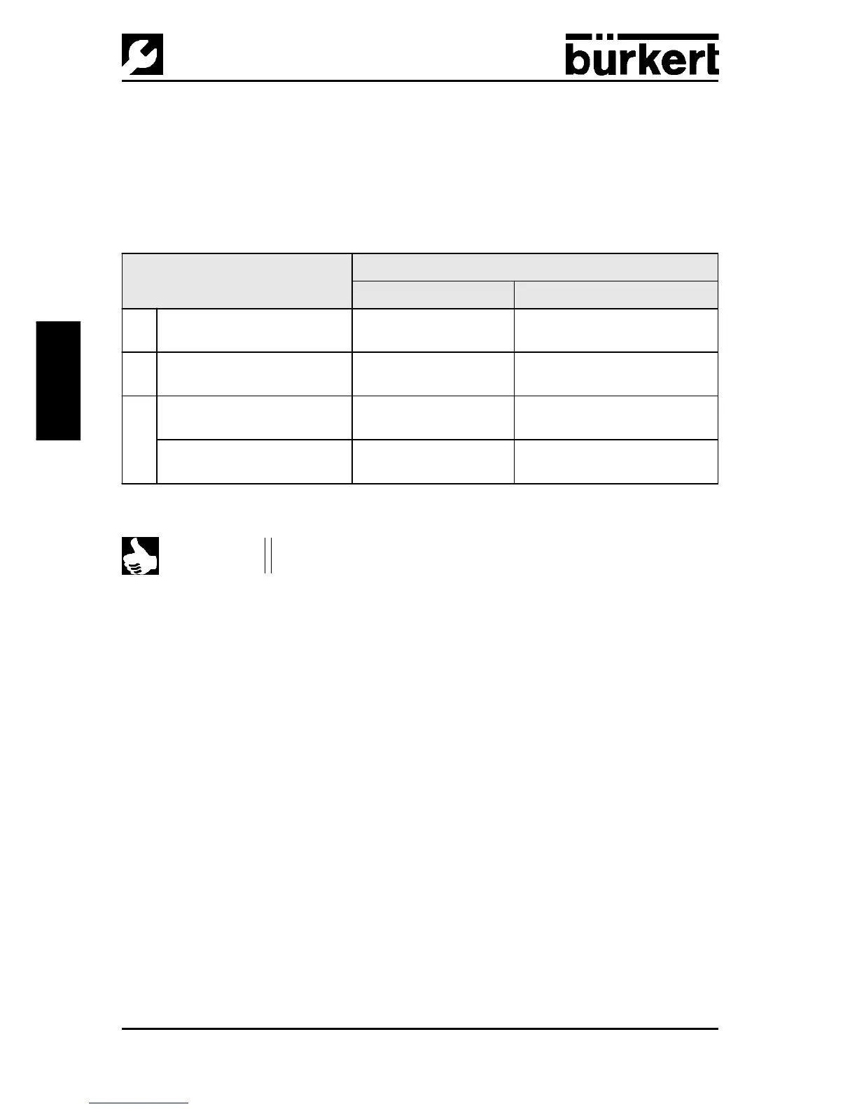
The control air will be connected according to the control function of the valve:
The waste air will escape via the silencer 3/R (see Fig. 1).
Please also comply with the instructions in the operating instructions and in the
data sheet of the valve!
Control function Pneumatic connection of Top
Control
with valve
Top
Control
outlet Process valve inlet
A
Process valve closed in rest
position (through spring)
2/A
1
(Port 2/A
2
not present)
Lower chamber of the drive
B
Process valve open in rest
position (through spring)
2/A
1
(Port 2/A
2
not present)
Upper chamber of the drive
I
Process valve closed in rest
position
2/A
1
2/A
2
Lower chamber of the drive
Upper chamber of the drive
Process valve open in rest
position
2/A
1
2/A
2
Lower chamber of the drive
Upper chamber of the drive
NOTE
In ”rest” position means that there is no voltage on the control
valves in the Top
Control
or that they have not been operated.
 Loading...


