EasyManua.ls Logo

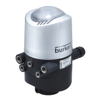
Burkert 8681 User Manual

Burkert 8681
166 pages
To Next Page IconTo Next Page
Page #1 background imageLoading...
Page #1 background image
Operating Instructions
Type 8681
Control Head
Designs: 24 V DC, 120 V AC, AS-i,
DeviceNet, IO-Link, büS/CANopen

Table of Contents

Other manuals for Burkert 8681

Questions and Answers:

Burkert 8681 Specifications

General IconGeneral
BrandBurkert
Model8681
CategoryController
LanguageEnglish

Summary

Operating Instructions

Symbols

Explains standard symbols used in the manual for warnings, notes, and procedures.

Authorised Use

Basic Safety Instructions

Explosion Protection Warnings

Details safety precautions for operating in potentially explosive atmospheres.

Electrical Safety Precautions

Outlines essential safety measures related to electrical shock risks.

General Hazardous Situations

Provides general safety guidelines to prevent injuries during operation.

Technical Data

Operating Conditions

Specifies environmental and operational parameters for the device.

Additional Warning Signs

Presents specific warning signs for approvals and operating conditions.

Device Reset Procedure

Explains how to perform a device reset to factory settings.

Assembly

Assembly Safety Instructions

Provides critical safety warnings and precautions for assembly procedures.

Control Head Assembly

Details the step-by-step procedure for assembling the control head.

Pneumatic and Electrical Connections

Guides the connection of pneumatic and electrical interfaces.

Opening and Closing the Housing

Safety Instructions for Housing

Highlights safety warnings related to opening and closing the device housing.

Pneumatic Installation

Pneumatic Safety Instructions

Covers critical safety warnings for pneumatic system installation.

Pneumatic Connections

Guides the proper connection of pneumatic lines to the control head.

24 V DC - DESIGN

Safety Instructions (24V DC)

Highlights safety warnings specific to the 24V DC electrical installation.

Electrical Installation (24V DC)

Guides the electrical installation process for the 24V DC version.

11 120 V AC - DESIGN

Electrical Connection Options (120V AC)

Details available electrical connection types for the 120V AC variant.

Safety Instructions (120V AC)

Highlights safety warnings specific to the 120V AC electrical installation.

Electrical Installation (120V AC)

Guides the electrical installation process for the 120V AC version.

12 AS INTERFACE - DESIGN

AS Interface Connection Options

Details the available connection types for AS interface communication.

AS Interface Safety Instructions

Highlights critical safety warnings for AS interface installation.

AS Interface Electrical Installation

Guides the electrical installation process for AS interface devices.

13 DEVICENET - DESIGN

DeviceNet Connection Option

Details the available connection type for DeviceNet communication.

Safety Position on Bus Failure

Describes safety actions when DeviceNet bus communication fails.

DeviceNet Safety Instructions

Highlights critical safety warnings for DeviceNet installation.

DeviceNet Electrical Installation

Guides the electrical installation process for DeviceNet devices.

Configuring DeviceNet Address and Baud Rate

Details the procedure for setting DeviceNet node address and baud rate.

DeviceNet Address Settings

Explains how to set the DeviceNet address using DIP switches.

DeviceNet Baud Rate Settings

Describes how to set the DeviceNet baud rate using DIP switches.

Safety Position on Bus Error

Describes safety actions for solenoid valves during a bus error.

14 IO-LINK - DESIGN

IO-Link Connection Options

Details the available electrical connection types for IO-Link devices.

IO-Link Electrical Installation

Guides the electrical installation process for IO-Link devices.

Safety Position on Bus Failure (IO-Link)

Describes safety actions for solenoid valves during IO-Link bus failure.

15 BÜS/CAN OPEN-DESIGN

Electrical Connection Options

Details the available electrical connection types for the bus.

Safety Position on Bus Failure (büS/CANopen)

Describes safety actions for solenoid valves during bus failure.

Installation Safety Instructions

Highlights critical safety warnings for installation procedures.

Electrical Installation (büS/CANopen)

Guides the electrical installation process for büS/CANopen devices.

Configuring Node ID and Baud Rate

Details the procedure for setting Node ID and baud rate.

Setting the Baud Rate

Describes how to set the baud rate using DIP switches or software.

Setting the Node ID

Explains how to set the Node ID (address) using DIP switches.

17 CABLING EXAMPLES (BÜS/CANOPEN)

18 CONNECTION OF AN EXTERNAL INITIATOR

Initiator Connection Safety

Highlights safety warnings for connecting external initiators.

Initiator Connection Procedure

Guides the step-by-step connection of external initiators.

19 SPECIAL DESIGNS

Control Head for Double-Acting Actuators

Describes the specific design for double-acting actuators.

Control Head (AS-i) with 2 External Initiators

Describes the AS-i variant with two external initiator connections.

20 POSITION MEASURING SYSTEM

Teach Functions Overview

Introduces manual and automatic teach functions for position setup.

Teach Functions and Reset

Explains manual teach functions and how to reset learned positions.

Automatic Teach Functions (Autotune)

Describes automated teach functions for various valve types.

21 LED COLOUR ASSIGNMENTS

22 SERVICE MODE / MANUAL OVERRIDE

Magnetic Manual Override

Details the function and operation of the magnetic manual override.

Mechanical Manual Override

Explains the use of the mechanical manual override for valve control.

23 MAINTENANCE, TROUBLESHOOTING

Maintenance Safety Instructions

Provides critical safety warnings for maintenance and troubleshooting tasks.

Safety Positions

Describes safety valve positions during power or bus failures.

Malfunctions Analysis

Helps diagnose and troubleshoot common faults and errors.

24 REPLACEMENT OF COMPONENTS AND MODULES

Replacement Safety Instructions

Highlights safety warnings prior to replacing components or modules.

Changing the Electronic Module

Provides step-by-step instructions for replacing the electronic module.

Changing the Valves

Details the procedure for replacing solenoid valve modules.

Changing the Position Measuring System

Guides the replacement process for the position measuring system.

25 SHUTDOWN

Shutdown Safety Instructions

Provides critical safety warnings for shutdown and disassembly procedures.

Related product manuals