40
24VDC - Design
10 24VDC - DESIGN
10.1 Electrical connection options
The following connection concepts are available for the electrical connection of the control head:
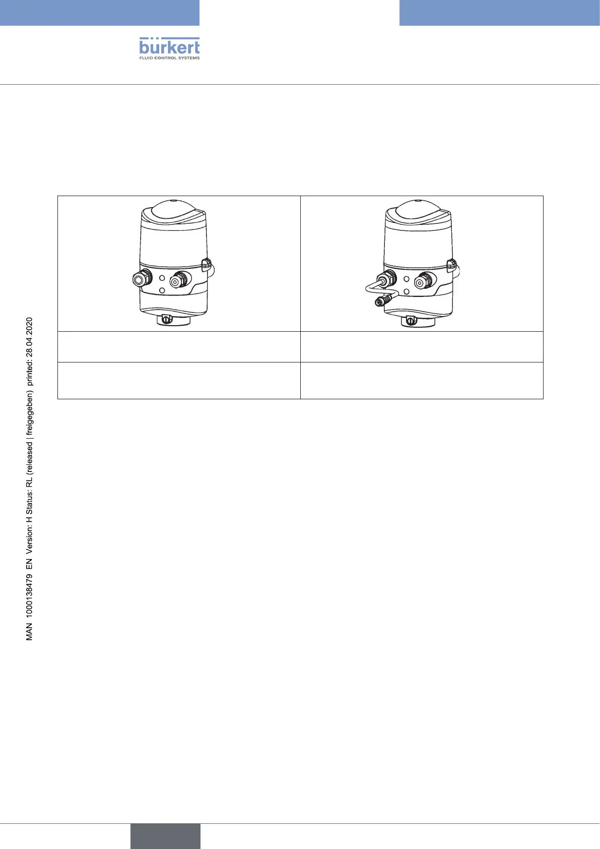
Cable gland Cable gland with multi-pole connection
(M12plugaccordingtoIEC61076-2-101,12-pole)
Connection left: Voltage, signals
Connection right: external initiator
Connection left: Voltage, signals
Connection right: external initiator
Fig. 14: Connection concepts 24 V DC
10.2 Electrical data
Power supply: 12 ... 28 V DC, residual ripple 10%
Connections:
Cable gland variant 1 x M16 x 1.5 cable gland/size22 - for power supply and signals,
(onlyfortransportationsafetydevicesealedwithdummyplugs,
removethesebeforeuse!)
for cable diameter 5 ... 10 mm,
for wire cross-sections 0.14 ... 1.5 mm
2
1 x M16 x 1.5 cable gland/size19 - connection option for external
initiator(sealedwithdummyplug,removethesebeforeuse)
Multi-poleconnectionvariant 1xM16x1.5cablegland/size22withmulti-poleconnection(M12
plugaccordingtoIEC61076-2-101,12-pole)forpowersupplyand
signals, cable length approx. 15 cm
1 x M16 x 1.5 cable gland/size19 - connection option for external
initiator(sealedwithdummyplug,removethesebeforeuse)
Power consumption (standby current): 30 mA at 24 V DC
english
Control Head Type 8681