159
Replacement of Components and Modules
Installation procedure:
→ Carefully insert the entire electronic module into the recess in the lower housing part.
→ Plug the electronic module carefully onto the contact pins for the position measuring system.
→ RefastentheelectronicmodulewiththeTorxT10screw(torque0.4Nm).
→ Reattach the electrical connections.
→ CheckDIPswitchpositions(4-switchblockforcolourcoding,8-switchblockonDeviceNetelectronic
moduleforaddressandBaudrate)andsetthepreviouslynotedswitchsettings,ifnecessary.
→ If necessary, set AS interface address and jumper positions.
→ Ifrequired,makesettingsagain,readoutbythePCserviceprogram,usingthePCserviceprogram.
→ PerformTeachprocedure(seechapter“20.1Settingthepositionmeasuringsystem(Teachprocedure)”
on page 130).
Besuretoworkcarefullyandcautiously,sothattheelectronicsarenotdamaged.
→ Close the housing following the instructions in chapter “8OpeningandClosingtheHousing”.
24.3 Changing the valves
Accordingtothedesign,0to3solenoidvalves(V1...V3)havebeeninstalledinthecontrolhead.The
solenoidvalveshavebeendesignedwiththeowrestrictionequipmentforintakeandexhaustairandmust
be installed as a valve module.
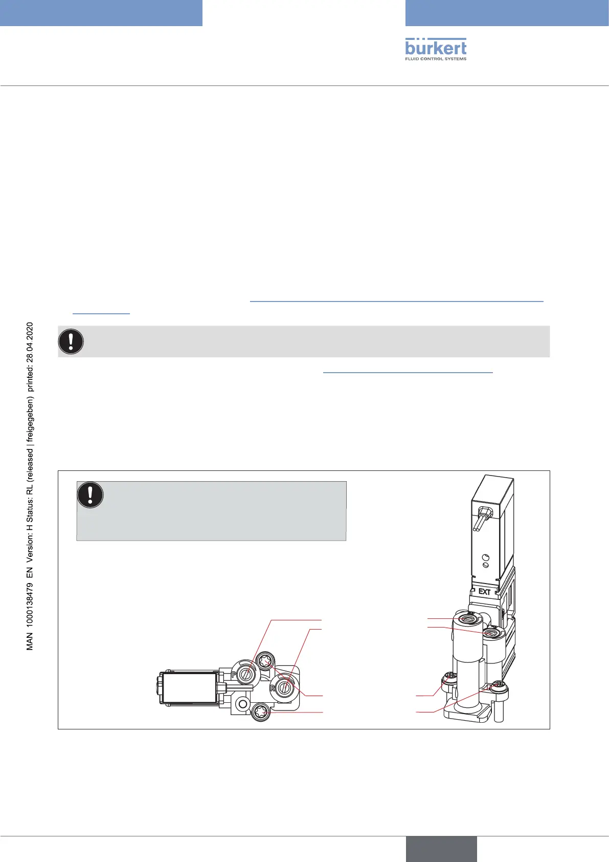
Valve module
from above
Flow restriction screws
Torxscrews(T10),
tighteningtorque:
1 Nm
Note:
Disassemble/assemble the valves in upright position, oth-
erwise there is a risk that the non-return valve will fall out!
Fig. 52: Valve module
english
Control Head Type 8681