28
Technical Data
6.8 Factory settings in the rmware
Thecontrolheadissuppliedwiththermwarefactorysettingsaslistedbelow.
Changestothefactorysettings for the classicvariants of Type 8681 (24VDC,120VAC,
AS-i,DeviceNet)
arepossibleviathePCserviceprogram(seesoftwaremanual:“SoftwaremanualType8681|PCservice
program”).
To do so, the control head is connected to the PC via the service interface on the electronic module – see
„Fig.9“.Thisinvolvesremovingtheplasticcover(seechapter„8“).
The service interface may only be used in non-explosive atmosphere, because the plastic hood
shouldberemoved(seechapter“8OpeningandClosingtheHousing”).
Changes to the factory settings for the
variantsDeviceNet,büS/CANopenandIO-Linkare usually pos-
sibleviathebus-speciccommunicationinterface.WithbüS/CANopenandIO-Link,changescanalsobe
carriedoutviatheBürkertCommunicator(Type8920).
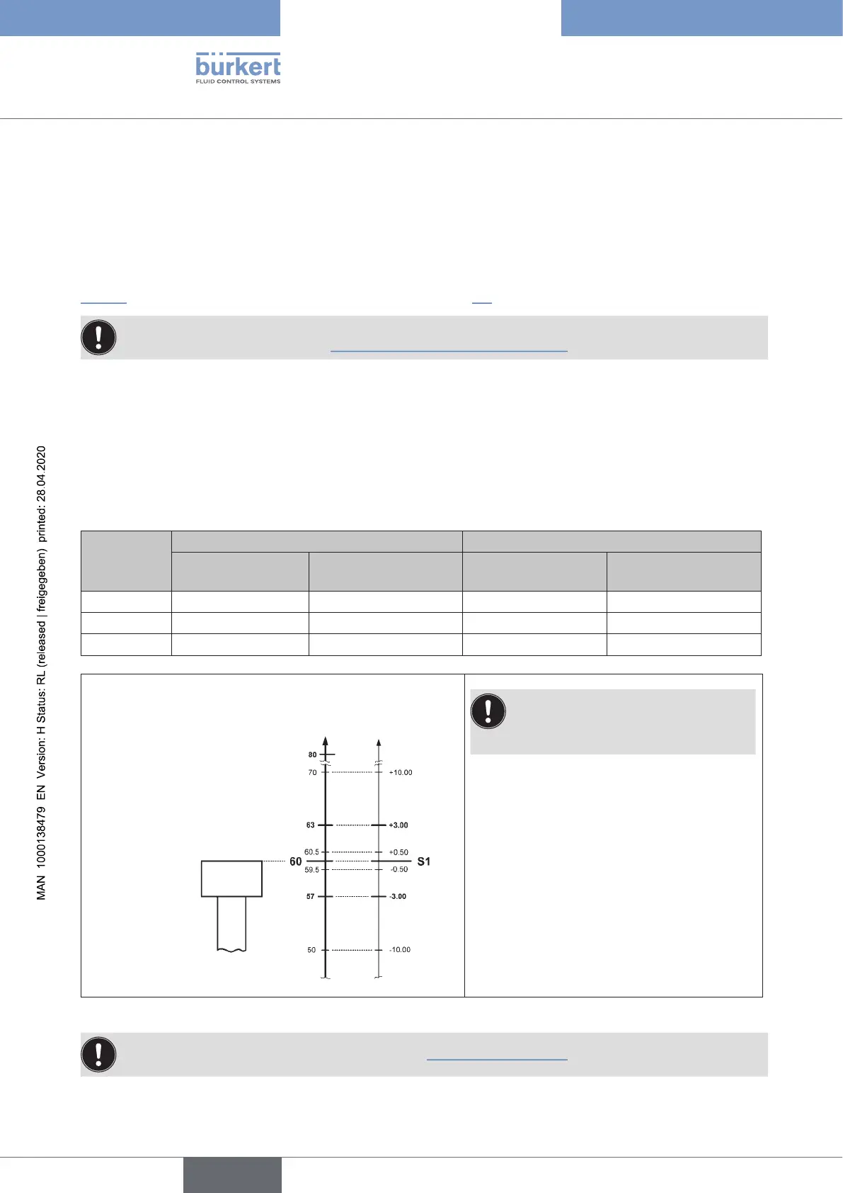
6.8.1 Feedback elds (position measuring system)
Afeedbackeldistheareawithinwhichavalveposition(e.g.S1)isreportedback.
Signal of
the valve
position
Feedback eld at top / positive Feedback eld at bottom / negative
Factory setting
[mm]
Adjustment range
[mm]
Factory setting
[mm]
Adjustment range
[mm]
S1 + 3.00 + 10.00 ... + 0.50 - 3.00 - 0.50 ... - 10.00
S2 + 3.00 + 10.00 ... + 0.50 - 3.00 - 0.50 ... - 10.00
S3 + 1.00 + 10.00 ... + 0.50 - 1.00 - 0.50 ... - 10.00
Stroke
[mm]
Feedback
eldS1
[mm]
Target
(Reference:
upper edge
ofthetarget)
Ensure that the teach points
includingtheirfeedbackeldsare
within the measuring range.
Fig. 8: Schematic diagram (not to scale) of the feedback elds, using the example of valve position S1
OverlapsofS1/S2/S3arepossible(seechapter“21.3Signalpriorities”).
english
Control Head Type 8681