95
büS/CAN open-Design
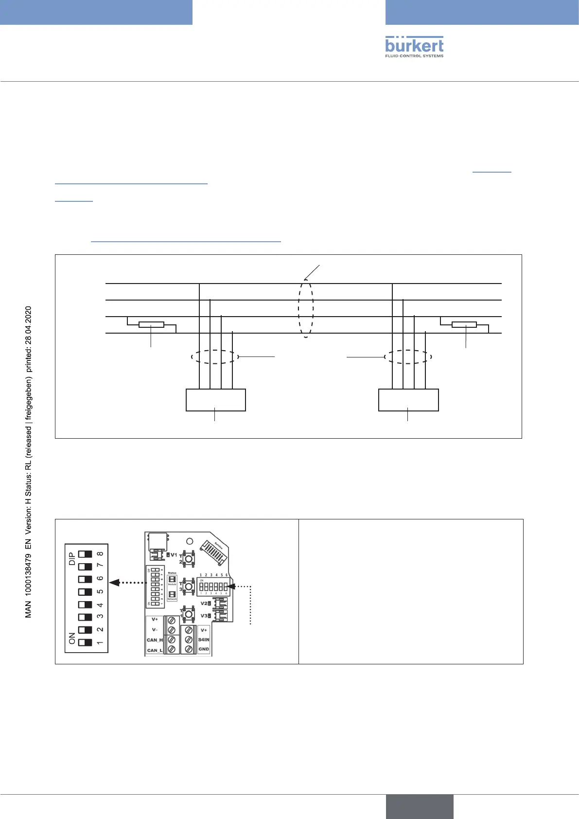
15.13 Network topology of a büS/CANopen system
When installing a büS/CANopen system, ensure that the terminating circuit of the data lines is correct. The
circuitpreventstheoccurrenceofinterferencecausedbysignalreectioninthedatalines.
Thetrunklinemustbeterminatedatbothendswith120Ωresistorsand1/4Wpowerloss-see“Fig. 43:
Networktopology-büS/CANopen”.
“Fig.43” illustrates a line with one trunk line and several drop lines. Trunk lines and drop lines consist of
identical material.
AuniqueNodeID(büS/CANopenaddress)canbeallocatedtoeachcontrolheadviaDIPswitches-see
chapter “15.14ConguringtheNodeID/baudrate”).
Trunk line
büS/CANopen cable
Terminating
resistor
120 Ω
¼ W
Terminating
resistor
120 Ω
¼ W
Drop lines
büS/CANopen
cable,
max. 6 m long
Node 01 Node n
Controlhead1(node1) Controlheadn(noden)
V +
V –
CAN_H
CAN_L
Fig. 43: Network topology - büS/CANopen
15.14 Conguring the Node ID/ baud rate
DIP switches for
colourcongura-
tion
DIP switches for
address+ baud rate
8DIPswitchesareavailableforconguration:
•DIPswitches1to6 fortheNodeID(büS/
CANopenaddress)
•DIP switches 7 to 8 for the baud rate
Please note:
ValuesxedbyDIPswitchesinvalidatesoftware-
conguredvalues!
Fig. 44: Position of the DIP switches
english
Control Head Type 8681