94
büS/CAN open-Design
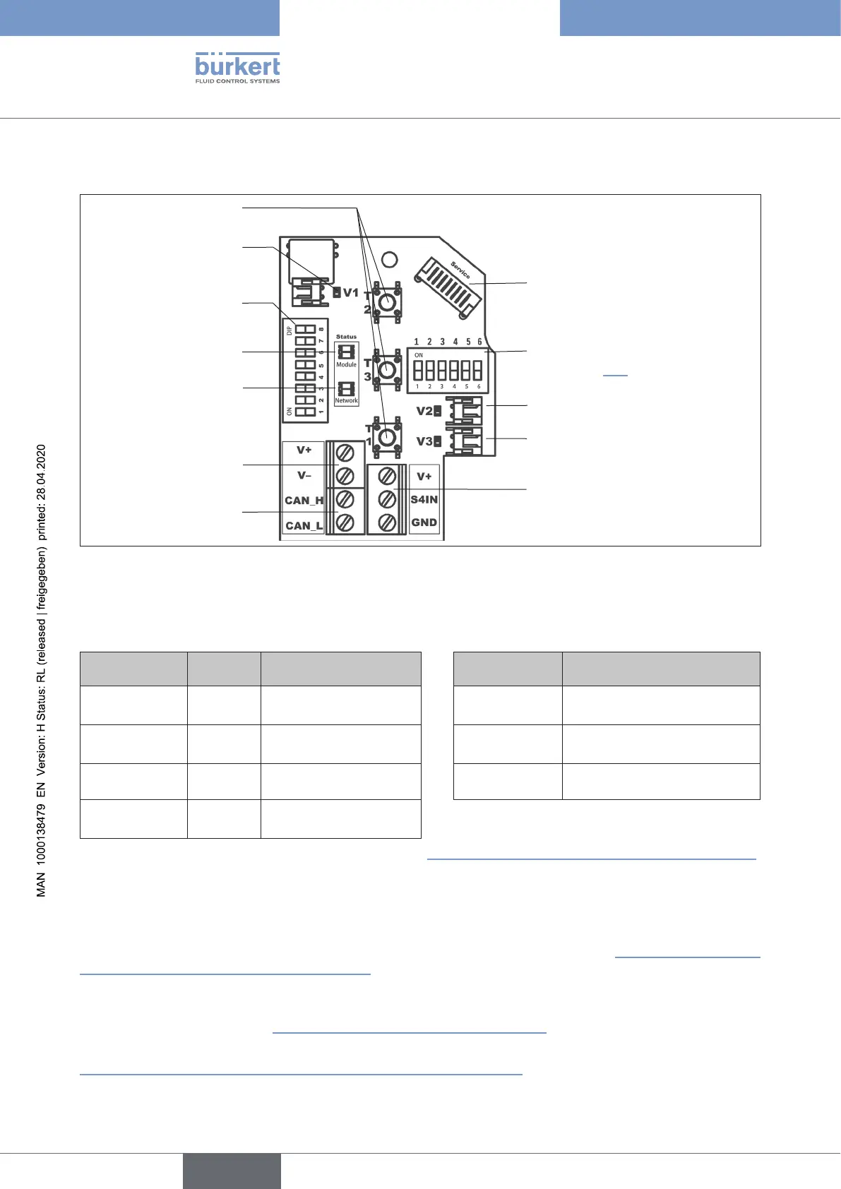
15.12.1 Electronic module büS/CANopen:
Solenoid valve connection
with status LED for valve V1
DIP switches for setting
address and baud rate
Service interface
DIP switches for colour coding
theTopLED(formoredetails
see chapter “21”)
Connection of the exter-
nal initiator
Power supply
büS/CANopen
Bussignals
Teach buttons T1-3
Solenoid valve connec-
tions with status LED
for valves V2, V3
Status LED for device
Status LED for network
Fig. 42: Electronic module büS/CANopen
15.12.2 Terminal strip conguration:
Designation
Terminal strip
Wire
colour
Assignment
Designation
Terminal strip
Assignment
V+ red
Power supply
büS/CANopen
V +
Power supply for external
initiator
V- black
Power supply
büS/CANopen
S4 IN External initiator input
CAN_H white
BussignalCANhigh GND GND external initiator
CAN_L blue
BussignalCANlow
For connecting the external initiator - compare chapter “18ConnectionofanExternalInitiator”onpage125.
15.12.3 Details on the DIP switches for colour coding:
The(classic)colourcombinationscanbesetviaDIP1to4asdescribedinchapter“21.1.1Devicespecic
LEDmode“8681ClassicMode””onpage138.ButonthisoccasionDIP5andDIP6havetobesetto“OFF”
to display the correct colours.
AsofrmwareB.02.00.00therearesoftwarecongurabledisplaymodesforthedevicestatusLED(TopLED)–
detailsarespeciedinchapter“21.1Displaymodi–overview”onpage136.
OtherparametersorcongurationsrequiretheuseoftheCANopenobjectlistorparameterlist-seechapter
“15.20.4Accesstofurtherparameters(cyclicandacyclic)”onpage117.
english
Control Head Type 8681