59
AS Interface - Design
12.8 Electrical installation of the AS interface
InternalcablingworkisnotrequiredforanyoftheASInterfacedesignswithmulti-poleconnection,which
makesinstallationandstart-uponsiteconsiderablyeasierandquicker,reducingtheriskofleaks.
However, you will require the correspondinglyassembled cable sets with the following pin assignments.
Likewise,thejumpersontheelectronicmodulemustbesetcorrespondingly(seeguresbelow).
NOTE!
Use of the control head in a potentially explosive atmosphere
` Onlyusecablesandcableglandswhichareapprovedfortherespectiveapplicationareaandtthe
cable glands according to the respective operating instructions!
` Close all unnecessary openings with lock screws/plugs approved for explosions area!
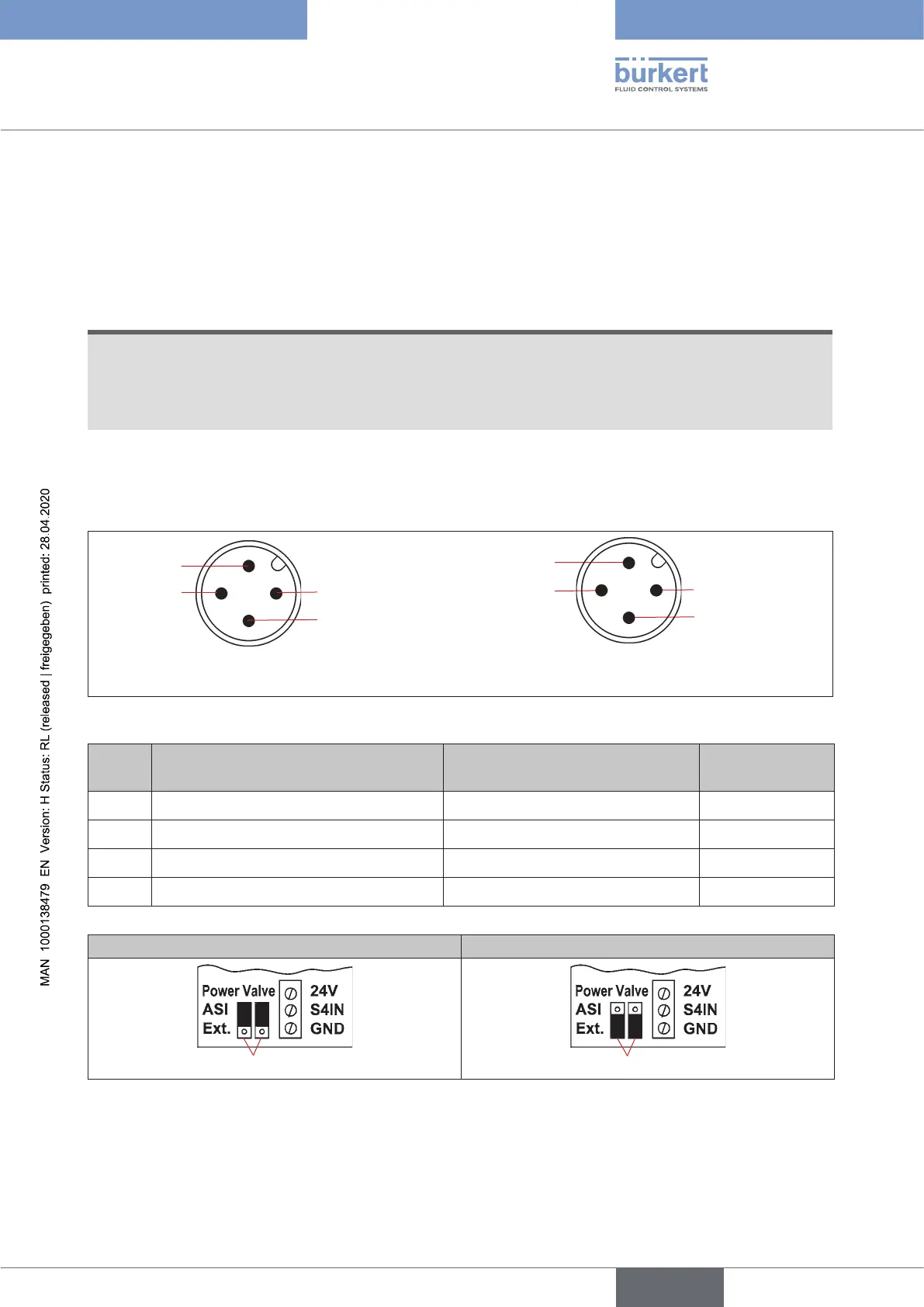
Bus connection for AS interface
(power supply for solenoid valves via bus or external power supply)
M12x1circularplug,4-pole,male(accordingtoIEC61076-2-101)
(viewoftheM12plug,fromthefrontontothepins)
Pin 2: NC
Pin 3: ASI - Pin 1: ASI +
Pin 4: NC
Busconnectionwithpowersupply
for solenoid valves via bus
Pin 2: GND
Pin 3: ASI -
Pin 1: ASI +
Pin 4: 24 V +
Busconnectionwithexternal
power supply via solenoid valves
Fig. 23: AS interface bus connection (power supply for solenoid valves via bus or external power supply)
Pin Conguration
(supply via bus)
Conguration
(external power supply)
Wire colour
1 AS interface - ASI+ AS interface - ASI + brown
2 Not used GND white
3 AS interface - ASI − AS interface - ASI − blue
4 Not used 24 V + black
Power supply of the solenoid valves via the bus External power supply of the solenoid valves
Jumper
Jumper
Fig. 24: Jumper setting on AS-i electronic module: Power supply to the solenoid valves via the bus or externally
Thecablewithmulti-poleconnectionvariantisespeciallysuitedfordirectandexibleconnectiontotheAS
interfacecableharnessusingtheribboncableterminal(M12branchcircuit,VAbranchcircuit)thatisoptionally
available.
english
Control Head Type 8681