160
Replacement of Components and Modules
Procedure:
→ Open the housing following the instructions in chapter “8OpeningandClosingtheHousing”.
→ If necessary, mark the electrical connections to ensure correct assignment during reinstallation.
→ Loosen the electrical connections.
→ Loosentheconnectingscrews(TorxT10)forthecorrespondingvalvemodule.
→ Take out the valve module and replace it with the spare part set.
→ Wheninsertingthevalvemodule,makesurethattheformsealtscorrectlyandfullyonthelowersideof
therespectivevalveange!
→ Fixthevalvemodule:todothis,insertthescrews(TorxT10)intotheexistingthreadingbyturningthem
backwardsandtightenthemtoatorqueof1.2Nm.
→ Reattach the electrical connections.
(Ifotherconnections,apartfromthesolenoidvalveconnections,havebeenremoved,readthecorre-
spondingchaptersontheelectricalinstallationoftherespectivevoltage/bus/connectionvariant)
→ Close the housing following the instructions in chapter “8OpeningandClosingtheHousing”.
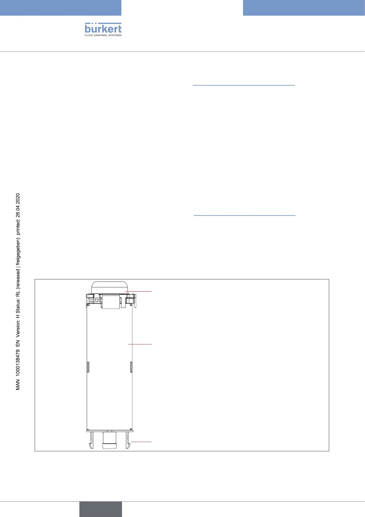
24.4 Changing the position measuring system
Thepositionmeasuringsystemconsistsofahousing,withaPCBmountedabovewithLEDsandlightcon-
ductor.Thereare4snap-thooks,whichsecurethepositionmeasuringsysteminthelowerhousingpart,by
snapping them into place.
PCBwithLEDsandlightconductor
(devicestatusLED/TopLED)
Housing of the position
measuring system
Snap-thooks(4x)
Fig. 53: Position measuring system
english
Control Head Type 8681