33
Assembly
7.2.2 Assembly sequence on the example of a double-seated valve
Procedure:
→ Mount the piston rod with the target on the process valve spindle. Observe reference dimensions!
→ Fastenthehubangeontheprocessvalve-see“Fig.10”.
During this, observe central alignment and sealing conditions!
→ Checkthesecuretofthesealingrings(intheupperandlowergrooves).
→ Mountthecontrolheadonthehubange(seamlessly360°rotatable).
→ Securecontrolheadwiththetwolockingscrews(shoulderscrewsM5)inthemiddlegrooveofthehub
angetopreventitfrombeingpulledothehubange–tighteningtorque:max.3.2Nm(see“Fig.10”
and “7.2.3Realignmentofthecontrolhead”).
7.2.3 Realignment of the control head
Ifnecessary,thecontrolheadcanberealigned(rotated),inparticularifproperlyaccessibleinstallationof
thepneumaticsupplylinesisnotpossibleduetospatialconditions.Thismightalsoberequiredforopera-
tionalaspects(accessibilityofthemanualoverride)andbecauseofelectricalconnectionpossibilities.
Procedure:
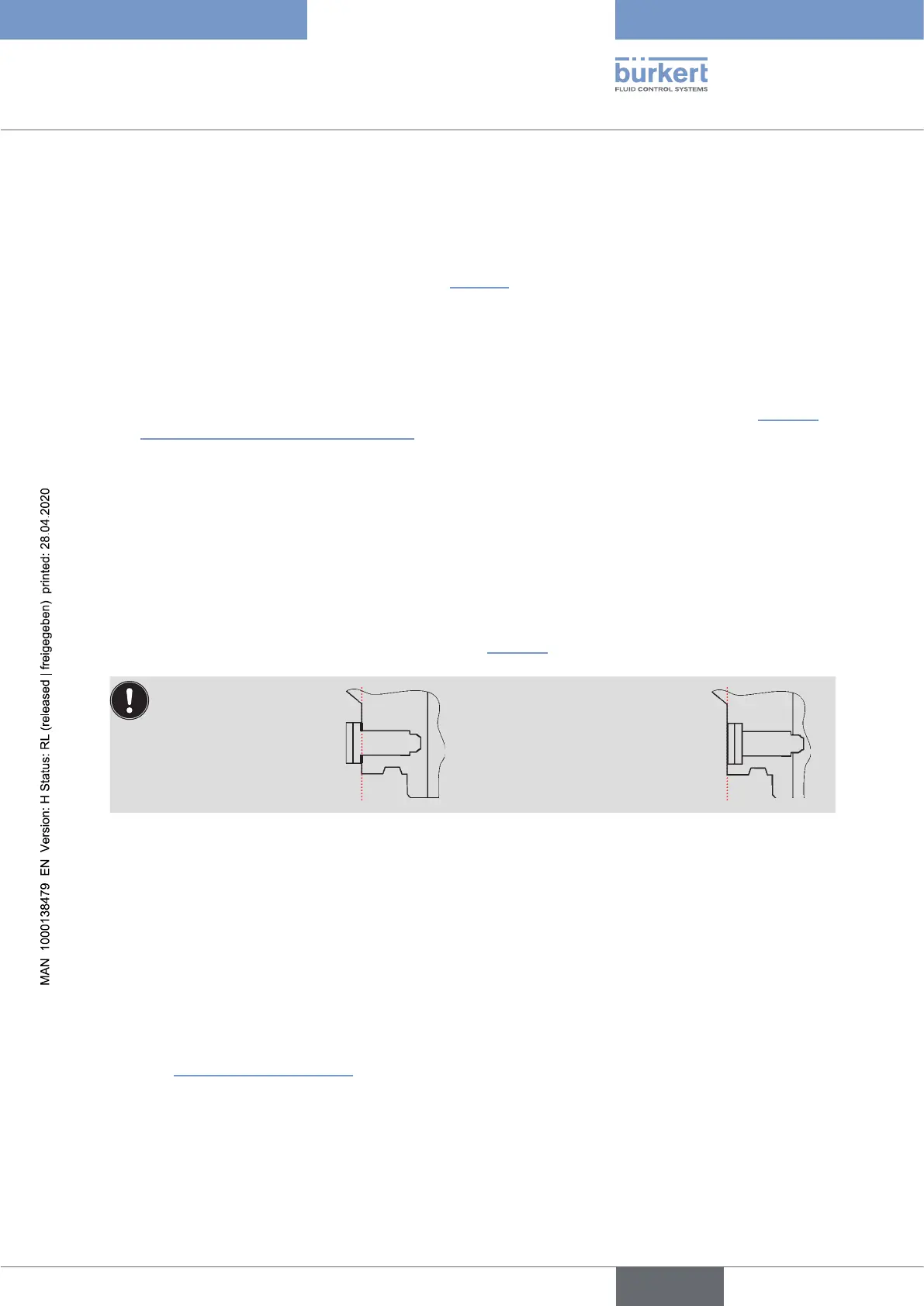
→ Loosenthelockingscrews(shoulderscrewsM5–see“Fig.10”)slightlyuntiltheundersideofthescrew
headisushwiththeauxiliarysurfaceofthehousing.
The locking screw has
beenloosenedsu-
ciently when the lower
side of the screw head
isushwiththeauxiliary
surface of the housing.
Thelockingscrewissuciently
tightened when the upper side of
thescrewheadisushwiththe
auxiliary surface of the housing.
Tightening torque: max. 3.2 Nm
→ Rotate the control head until the desired alignment has been achieved.
→ Securethecontrolheadwithlockingscrewsagainuntiltheuppersideofthescrewheadisushwith
the auxiliary surface of the housing. The locking screws have no sealing function. The control head is not
xedinplacebythelockingscrewsbutismerelysecuredagainstbeingpulledothehubange.
7.2.4 Assembly of the pneumatic and electrical connections
Pneumatic installation
see chapter
“9PneumaticInstallation”
english
Control Head Type 8681