140
LED Colour Assignments
21.1.3 Valve mode
ThedevicestatusLED(TopLED)displaythepositionfeedback(S1,S2,S3)oftheprocessvalveandthe
feedback S4IN from the external initiator. There is no display of error and warning messages in this mode.
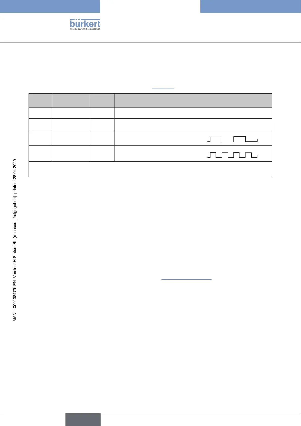
The position feedback is displayed as shown below in
“Table10”.
Position Process valve
position, e.g.:
Colour Flashing pattern of the position feedback
S1 closed green *) continuously lit
S2 open yellow *) continuously lit
S3 cycle stroke green *)
continuouslyashingslowly**)
(250msON,250msOFF)
S4IN ext. Initiator,
active
green *) continuouslyashingquickly**)
(125msON,125msOFF)
Ifthereisnopositionfeedback(S1toS4IN),i.e.theprocessvalveisinintermediatepositionsofthe
denedteachpoints,theTopLEDiso*) ***).
Table 10: Description of the colours and ashing patterns in “valve mode” display mode
*) Factorysettings(otherselectablecoloursforS1toS4INandalsofortheintermediatepositions:
white,green,blue,yellow,orange,red,(Top)LEDo)
**) Factorysettings(otherselectableashingpatterns:[continuouslylit],[125msON+125msOFF],
[250msON+250msOFF])
***) Flashing pattern for the selected colour for the intermediate positions: continuously lit
For IO-Link devices:
TheinformationrequiredforcongurationcanbefoundintheIODDobjectdescriptionunderobject“LED
modi”(0x2120).
For büS/CANopen devices:
ThisdisplaymodecanbeconguredbysoftwareasofrmwarerevisionB.02.00.00(DIP1to6:111110)or
canbexedusingDIPswitches(DIP1to6:011110)–see“Table6”onpage137.
english
Control Head Type 8681