82
IO-Link - Design
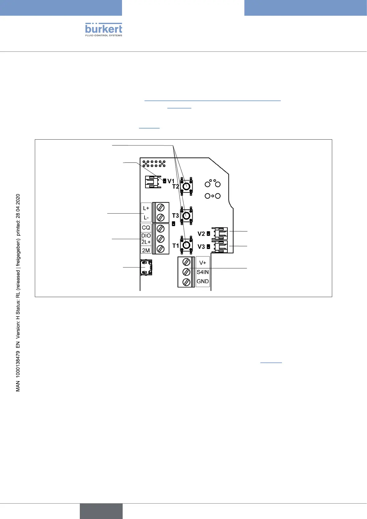
14.5.4 Electrical installation – IO-Link
For the versions with cable glands:
→ Openthehousing(comparechapter“8OpeningandClosingtheHousing”onpage35)sothatthe
electronicmoduleisvisibleasshownbelow(“Fig.36”).
→ Connectthedierentwiresofthecable(unshielded3-or5-linestandardlines)totheconnectionterminalson
the left side as described in chapter “14.5.5”.TheassignmentconformstotheIO-Linkspecication.
Solenoid valve connection
with status LED for Valve V1
Connection of the exter-
nal proximity switch
Micro-USBportfor
servicepurposes(büS)
Teach buttons T1-3
Solenoid valve connec-
tions with status LED
for Valves V2, V3
Port for Power 1
Ports for C/Q and
Power 2
(2L+,2MforportclassB)
Fig. 36: Electronic module IO-Link (in the example: port class B)
For the multi-pole connection variants:
NointernalcablingworkisrequiredforanyoftheIO-Linkversionswithmulti-poleconnectionwhichmakes
installationandstart-uponsiteconsiderablyeasierandquicker,reducingtheriskofleaks.
Thecontrolheadfeaturesamulti-polecircularplug(M12x1-,4-or5-pole,male)toacable15cminlength.The
assignmentcorrespondstotheIO-Linkspecication,orseealsothenextchapter“14.5.5”).
english
Control Head Type 8681