16
System Description
5.3 Functions / options / variants
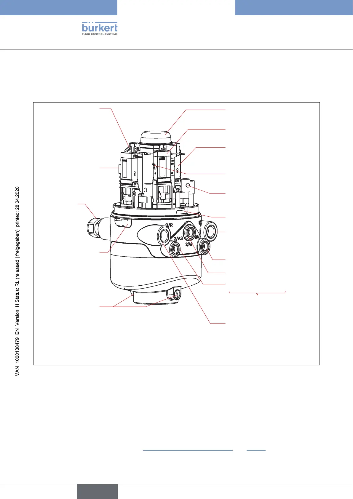
5.3.1 Structure of the control head
Electronic module with
connection terminals,
service interface and
Teachbuttons(rear
side)
Solenoid valve V3 *)
Solenoid valve V1 *)
Solenoid valve V2 *)
Cable glands
(rear)
Exhaustairconnection(3/R)
Mechanical manual override
(redlever)
Supplypressureconnection(1/P)
Working connections
(2/A1...3)
Flowrestrictionscrew(s)for
PandR(2persolenoidvalve)
Solenoidvalve3(2/A3)
Solenoidvalve2(2/A2)
Solenoidvalve1(2/A1)
Position measuring system with
LED(devicestatusLED/TopLED)
Silencer in the exhaust air
connection(3/R),notshown
Sealing lug
(onlowerhousingpart)
2lockingscrews
(shoulderscrewsM5).
No sealing function,
merely as protection
againstpullingofrom
thehubange
Lockinggroove(3x)
Fig. 1: Structure of control head Type 8681 (with 3 solenoid valves)
____________________________________________
*)
If the solenoid valve is not present, the connection is sealed tightly with a cover plate.
Controlheadversionswithoutsolenoidvalves(i.e.“feedbacktop”)donothaveanypneumaticconnec-
tions at the housing, see also chapter “5.3.3Numberofsolenoidvalves” and “Fig.5”.
english
Control Head Type 8681