32
Assembly
7.2.1 Hub ange / Adapter
FortheinstallationofthecontrolheadType8681toaprocessvalve(spindle),youwillrequireaprocess
valve-specichubangeasanadapter.
Thehubangemustbeadaptedtothedesignoftheprocessvalveandproducethemechanicalcon-
nection between the process valve and the control head. The axial fastening is done by two locking screws
(shoulderscrewsM5),whichengageinthemiddlegrooveofthehubange(protectionagainstpullingo).
The control head can radially slide into any position in 360° arc, seamlessly.
Thehubangeandthenon-ferromagnetic piston rod with the ferromagnetic target, which serves to
detecttheprocessvalvepositionmustcomplywiththespecicationsregardingmaterialanddimensional
accuracy – see chapter “6.7Positionmeasuringsystemdata”.
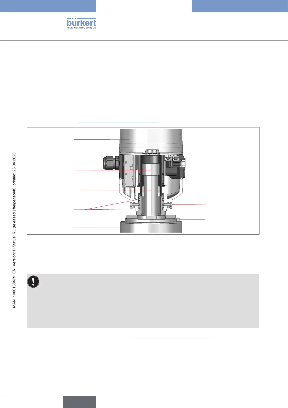
Control head
Process valve
Target made
of 1.4021
O-rings
Hubange
Locking screws
(2xM5)
Piston rod (*)
(max.Ø30)
Fig. 10: Schematic diagram of the control head - process valve adaptation
(*) The fastening materials for target and piston rod as well as the piston rod itself shall not be made of
materialwithverygoodelectricalconductivity(e.g.copper,aluminum)orofferromagneticmaterial.
Stainlesssteelwithoutferromagneticpropertiesissuitable(ifnecessary,checkaftermachining).
•To ensure the proper function of the position measuring system, the axial deviation of the adapter
must be less than ± 0.1 mm to the spindle when mounted!
•
UseBürkertadaptionsexclusively.
•Priortoassemblingthecontrolheadontothehubange,lightlygreasetheO-ringswithasilicone
grease.
•The hood must be lead-sealed in the potentially explosive atmosphere to prevent the housing
from being opened without a tool!
For dimensional relationships, see also chapter
“6.7Positionmeasuringsystemdata”.
english
Control Head Type 8681