80
IO-Link - Design
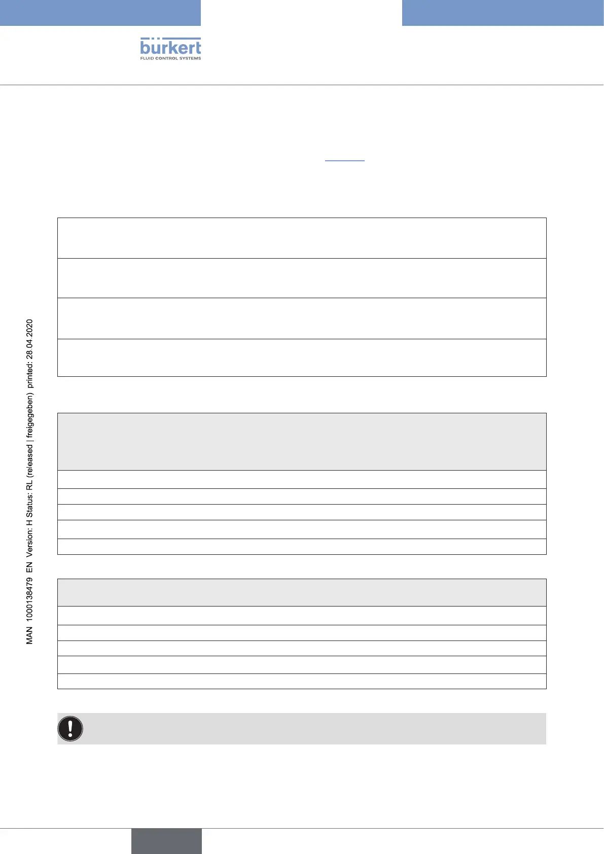
14.5.3 Design aid
Thevaluesweredeterminedforthedesignvoltageof24VDC.Thedierentpowersupplyofthesystem
andactuators(solenoidvalves)forportclassAandB(see“Fig.37”)mustbetakenintoconsiderationwhen
designing the voltage sources.
Power/current consumption for port class A:
Power consumption of the electronics:
P
el
=1.0W or I
el
=42mA at 24 V
Power consumption of a valve during activation (200 ms):
P
valve ON
=0.9W or I
valve ON
=38mA at 24 V
Power consumption of a valve after reduction:
P
valve
=0.6W or I
valve
=25mA at 24 V
Power consumption of an optical position feedback:
P
LED
=0.5W or I
LED
=21mA at 24 V
Calculation examples (for port class A):
Example 1:
3valvesareactivated,onepositionisreported(statusfor200ms):thecontrolheadswitchesautomaticallyone
valve after another to keep the current consumption low - i.e.: max. current consumption I
Total l, max.
=currentcon-
sumptionof2valves(alreadyactivated)+1valve(justswitching)
P
Total
=P
el
+ 2 x P
valve
+ 1 x P
valve ON
+ 1 x P
LED
3.6 W =1.0W + 2 x 0.6 W + 1 x 0.9 W + 1 x 0.5 W
or
I
Total
@ 24 V =I
el
+ 2 x I
valve
+ 1 x I
valve ON
+ 1 x I
LED
151 mA =42mA + 2 x 25 mA + 1 x 38 mA + 1 x 21 mA
Example 2:
3valveshavebeenactivated,onepositionisreported(persistentstate):
P
Total
=P
el
+ 3 x P
valve
+ 1 x P
LED
3.3 W =1.0W + 3 x 0.6 W + 1 x 0.5 W
or
I
Total
@ 24 V =I
el
+ 3 x I
valve
+ 1 x I
LED
138 mA =42mA + 3 x 25 mA + 1 x 21 mA
Whenusinganexternalproximityswitch,itspowerrequirementshouldbeadded.
english
Control Head Type 8681