47
120VAC - Design
11 120VAC - DESIGN
11.1 Electrical connection options
Cable gland:
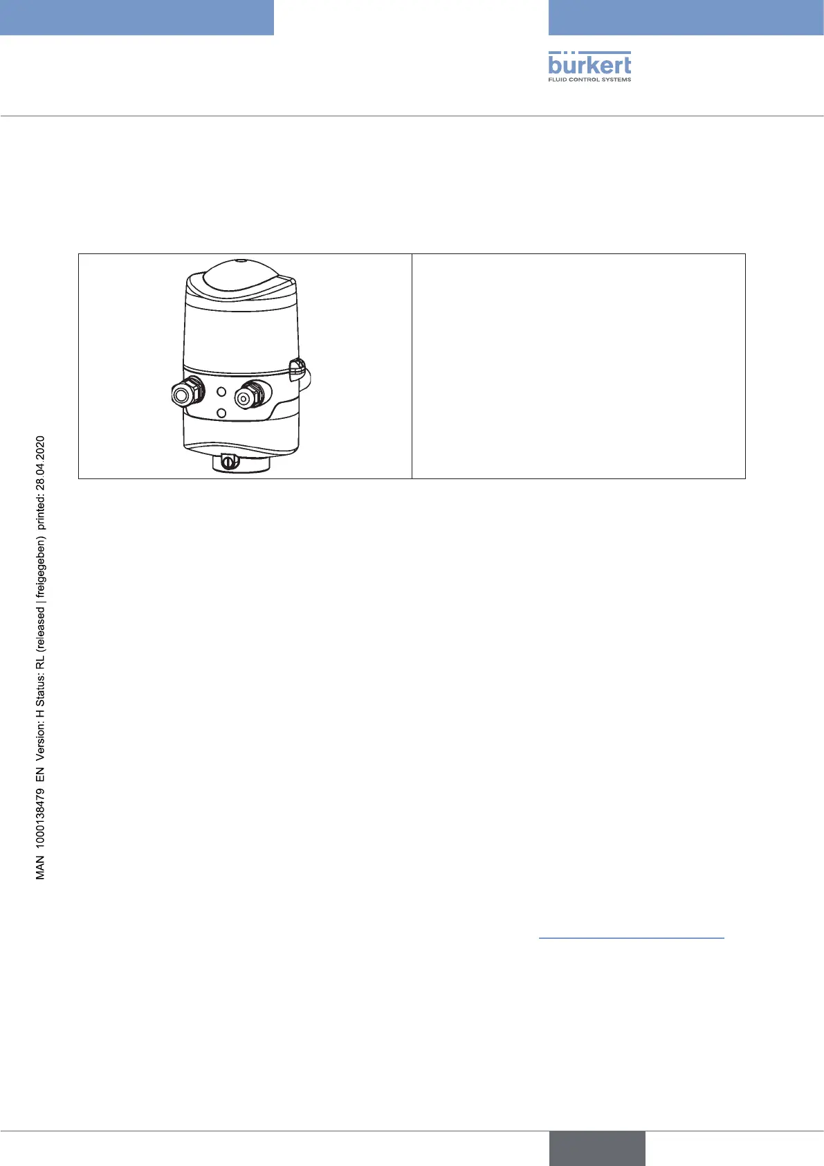
Connection left: Voltage, signals
Connection right: external initiator
Fig. 18: Connection concept 120 V AC
11.2 Electrical data
Central power supply: 110 ... 130 V AC, 50/60 Hz
Connections: Cable gland 1 x M16 x 1.5 cable gland/size22 - for power supply and signals
(onlyfortransportationsafetydevicessealedwithdummyplugs,
removethesebeforeuse!)
for cable diameter 5 ... 10 mm,
for wire cross-sections 0.5 ... 1.5 mm2 ,
including PE connection terminal
(tighteningtorqueoftheclampingscrewsmax.0.5Nm)
1 x M16 x 1.5 cable gland/size19 - connection option for external
initiator(sealedwithdummyplug,removethesebeforeuse)
Power consumption (standby current): 10 mA at 120 V AC
Solenoid valves:
Max.switchingcapacity: 1.7VA(persolenoidvalve)
Typ.continuousoutput: 1.4VA(persolenoidvalve)
Power consumption per solenoid valve: 12 mA at 120 V AC
Operatingmode: Long-termoperation(100%ED)
Central display of the switching statuses: 13 mA with a power supply of 120 V AC per illuminated
display;
colour switching see chapter “21LEDColourAssignments”
Outputs/binary feedback signals: S1out - S3out
Design: Normally open contact, L switching,
short-circuit protection via automatically resetting fuse
Switchable output current: max. 50 mA per feedback signal
Outputvoltage-active: ≥(operatingvoltage-2V)
Output voltage - inactive: max. 1 V in unloaded state
english
Control Head Type 8681