141
LED Colour Assignments
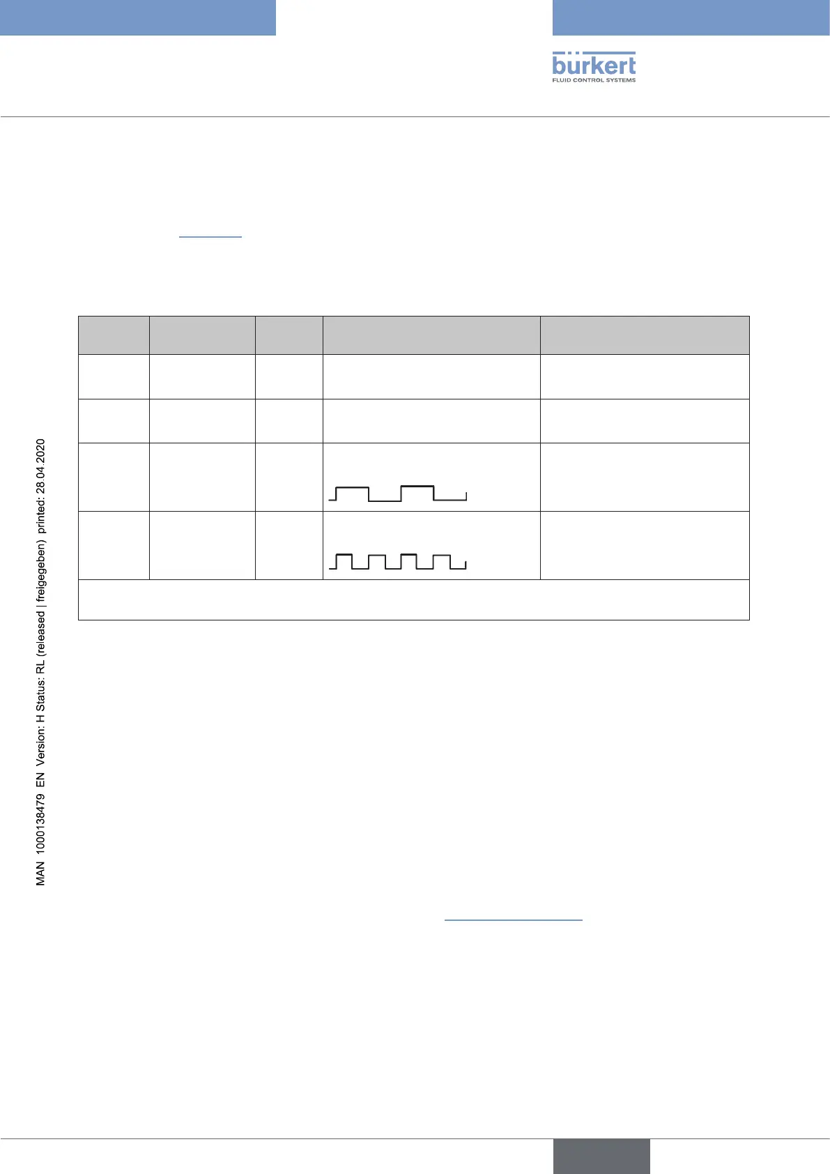
21.1.4 Valve mode + Errors
ThedevicestatusLED(TopLED)displaythepositionfeedback(S1,S2,S3)oftheprocessvalveandthe
feedback S4IN from the external initiator as well as error messages. The position feedback is displayed as
shown below in “Table11”.
If an error
(i.e.internalerror,buserror,errorwithmanualorautomaticTeachfunction,positionsmeasuring
systemsignalerror)occurs,thisisalsodisplayedalternatelyaccordingtothescheme:
1 second position feedback / 1 second error display.
Position Process valve
position, e.g.:
Colour Flashing pattern of the
position feedback
Fault indication
S1 closed green *) continuously lit is lit red alternating with colour
from S1
S2 open yellow *) continuously lit is lit red alternating with colour
from S2
S3 cycle stroke green *)
continuouslyashingslowly**)
(250msON,250msOFF)
is lit red alternating with colour
from S3
S4IN ext. Initiator,
active
green *)
continuouslyashingquickly**)
(125msON,125msOFF)
is lit red alternating with colour
from S4IN
Ifthereisnopositionfeedback(S1toS4IN),i.e.theprocessvalveisinintermediatepositionsofthe
denedteachpoints,theTopLEDiso*) ***).
Table 11: Description of the colours and ashing patterns in “valve mode + errors” display mode
*) Factorysettings(otherselectablecoloursforS1toS4INandalsofortheintermediatepositions:
white,green,blue,yellow,orange,red,(Top)LEDo)
**)Factorysettings(otherselectableashingpatternsare:[continuouslylit],[125msON+125msOFF],
[250msON+250msOFF])
***) Flashingpatternfortheselectedcolourfortheintermediatepositions:continuouslylit(alternatingwith
possibleerrormessages)
For IO-Link devices:
TheinformationrequiredforcongurationcanbefoundintheIODDobjectdescriptionunderobject“LED
modi”(0x2120).
For büS/CANopen devices:
ThisdisplaymodecanbeconguredbysoftwareasofrmwarerevisionB.02.00.00(DIP1to6:111110)or
canbexedusingDIPswitches(DIP1to6:101110)–see“Table6”onpage137.
english
Control Head Type 8681