158
Replacement of Components and Modules
24.2 Changing the electronic module
NOTE!
Electrostaticsensitivecomponents/modules!
•Thedevicecontainselectroniccomponentswhichreactsensitivelytoelectrostaticdischarge(ESD).Contact
with electrostatically charged persons or objects may be hazardous to these components. In the worst
case scenario, they will be destroyed immediately or will fail after start-up.
•
ObservetherequirementsinaccordancewithDINEN61340-5-1tominimiseoravoidthepossibilityof
damage caused by sudden electrostatic discharge!
•Also ensure that you do not touch electronic components when the operating voltage is on!
Removal procedure:
→ Open the housing following the instructions in chapter “8OpeningandClosingtheHousing”.
→ If necessary, mark the electrical connections to ensure correct assignment during reinstallation!
→ If necessary, note the position of the 4 DIP switches for the set colour code and on the DeviceNet
electronicmoduletheDIPswitches(8-switchblock)forBaudrateandaddress.OntheAS-ielectronic
module,notetheASinterfaceaddressandthejumperpositions(powersupplytoASinterface).
→ Ifrequired,readoutandnotespecialsettingsbythePCserviceprogram.
→ Loosenallelectricalconnectionsontheelectronicmodule(plug-typeconnections,screw-typeterminal
connections).
→ Loosenthescrew-typeconnection(TorxT10screw)oftheelectronicmoduleandstorethescrewinasafe
place.
→ Carefully press the electronic module forwards so that the contact pins on the position measuring
system are exposed.
→ Carefully lift the electronic module upwards.
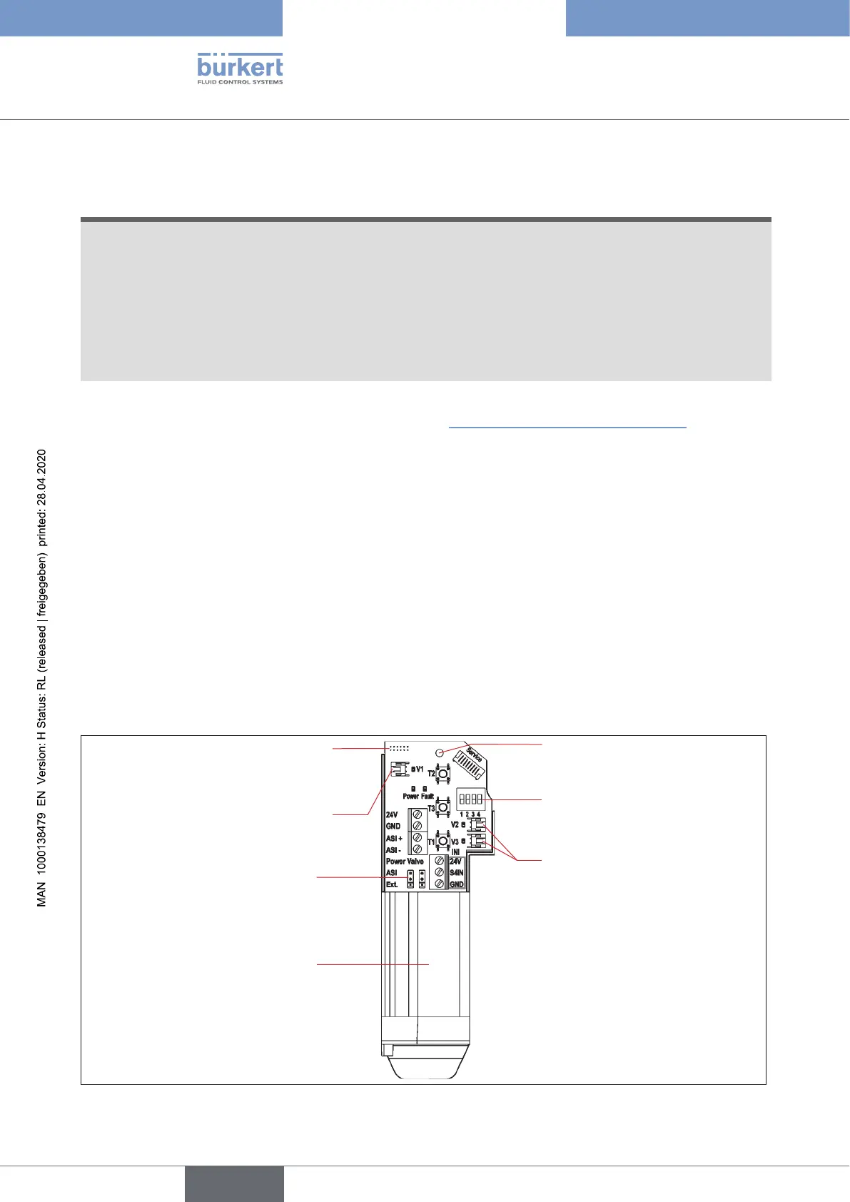
4 DIP switches for
colour coding
Fastening screw
(Torx10)
Connection for the position
measuring system's contact
pins
Electronic module,
complete(lowerpartcast,
readyforinstallation)
Plug-in connectors
for valves V2 and V3
Jumper for AS interface
power supply
Plug-in connector for valve
V1
Fig. 51: Electronic module (here example of AS interface)
english
Control Head Type 8681