60
AS Interface - Design
The optional ribbon cable terminal contacts the AS interface cable harness by means of penetration technology
which allows installation by "clipping in" the AS interface cable harness without cutting and without removing
insulation.
Screw, 2x
Branchcircuit
M12 plug-in
connector
Procedure:
→ Open the ribbon cable terminal
(loosenscrewsandremovecover)
→ Insert cable harness
→ Close ribbon cable terminal again
→ Tighten the screws
Loosen the thread-forming screws slightly and position
them on the existing threaded hole and screw in.
Fig. 25: Optional ribbon cable terminal for AS interface cable harness
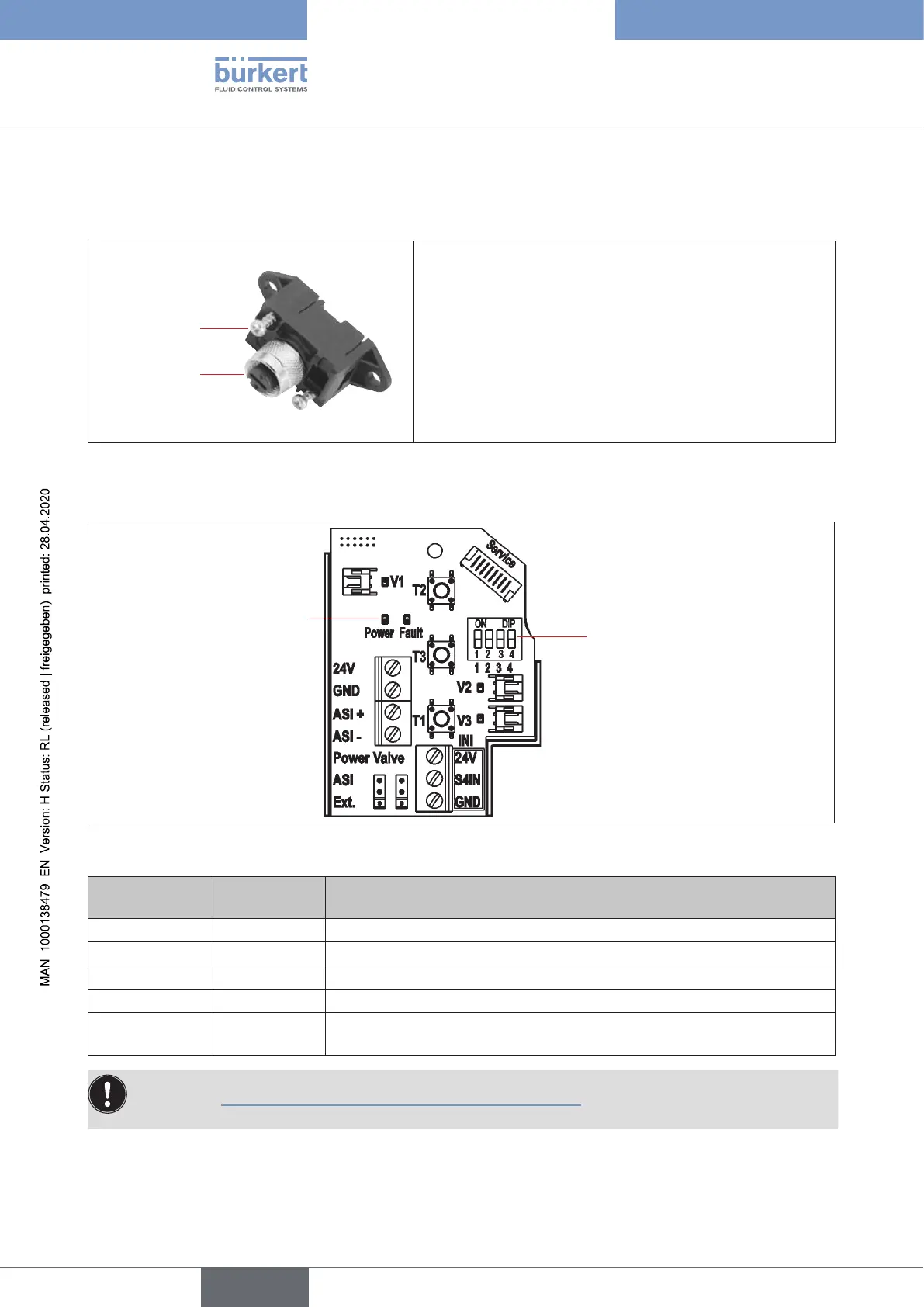
AS interface electronic module - LED status displays:
4 DIP switches
for colour coding of the
device status LED /
Top LED
LED status displays
"Power" and "Fault"
Fig. 26: LED status displays on the AS-i electronic module
LED 1 "Power"
(green)
LED 2 "Fault"
(red)
signalised status
o o Power OFF
on
o OK
on on
Nodatatrac(expiredWatchdogatslaveaddressdoesnotequal0)
ashing on Slaveaddress=0
ashing ashing Sensorsupplyoverload/manualactuationactivated/“untaught”/
service/maintenancerequest/PCserviceprogramservicemode
Thecentralmulti-colourstatusdisplay(devicestatusLED/TopLED)ashesalsointhefaultcolour
(seechapter“21.2Flashingpattern&faultsignalling”onpage143),ifthestatusLED2“Fault”onthe
electronic module is active.
english
Control Head Type 8681