39
Pneumatic Installation
Settings of the ow-rate or the control speed with the help of the ow restriction
screws:
For proper setting, it is advisable to turn the twoowrestrictionscrewsinitiallyintotheminimum
ow-rateposition. The process valve will then initially move slowly so that you have more time to
ndtheoptimumsettingduringaswitchingoperation.
Minimisingtheowrate: Turnclockwise
Maximisingtheowrate: Turncounterclockwise
→ Open the housing following the instructions in chapter “8OpeningandClosingtheHousing”.
→ Observingthesafetyguidelines,activatetherespectivevalvelocation(V1,V2orV3)tobeset(either
usingthesystemcontrol(PCserviceprogrammorBürkertCommunicator)ortherespectivemanual
overrides on the solenoid valve - “Fig.13”).
→ Turntheowrestrictionscrew"P"counterclockwisetosettherequiredowrateandthereforethe
openingtimefortheprocessvalve.(Tool:at-bladescrewdriver,width≤3mm).
→ Subsequentlydeactivatetherespectivevalvelocation(V1,V2orV3).
→ Turntheowrestrictionscrew"R"counterclockwisetosettherequiredowrateandthereforethe
closing time for the process valve.
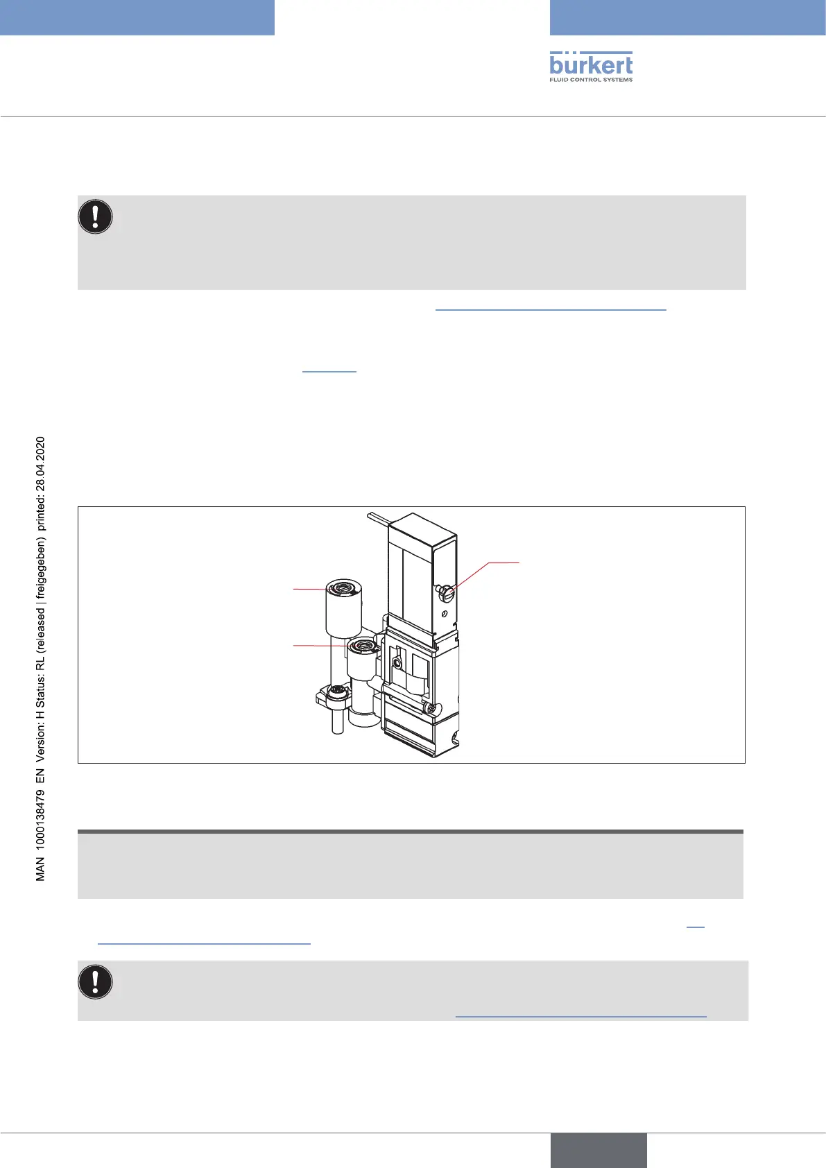
Flow restriction screw
Exhaust air R
Flow restriction screw
Intake air P
Red hand lever of the
mechanical manual
override:
Hand lever position:
left: 0
right: 1
Fig. 13: Flow restriction screws and mechanical manual override of the solenoid valves
NOTE!
To avoid unintentional switching of the process valve:
•
Makessurethatallmanualoverrideshavebeendeactivated(handleverallthewayleft,aspictured)
after the setting work has been completed!
→ Ifnofurtherinstallationworkisrequired,closethehousingfollowingtheinstructionsinchapter“8
OpeningandClosingtheHousing”.
If no system status is available during setting, readjust the system under system operation conditions
if necessary.
Observe the safety guidelines during this! See chapter
“3BasicSafetyInstructions”onpage12.
english
Control Head Type 8681