48
VI. Gas Piping
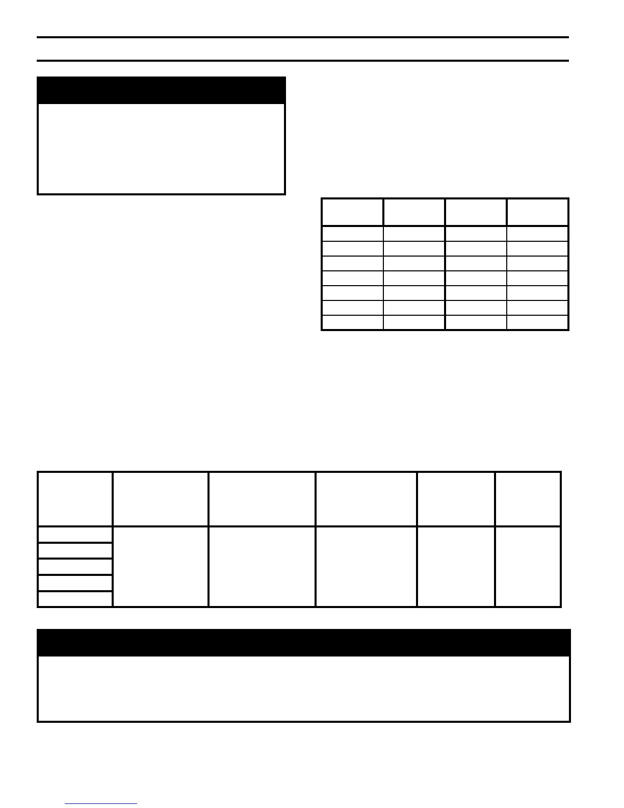
Table 5: Gas Ratings
For materials or conditions other than those listed
above, refer to National Fuel Gas Code, NFPA54/ANSI
Z223.1, or size system using standard engineering
methods acceptable to authority having jurisdiction.
B. Connect boiler gas valve to gas supply system.
Table 6: Specic Gravity Correction Factors
A. Size gas piping. Design system to provide adequate gas
supply to boiler. Consider these factors:
1. Allowable pressure drop from point of delivery to
boiler. Maximum allowable system pressure is ½
psig. Actual point of delivery pressure may be less;
contact gas supplier for additional information.
Minimum gas valve inlet pressure is stamped on the
rating label located in the boiler’s vestibule com-
partment.
2.
Maximum gas demand. Refer to the boiler’s input as
printed on it’s rating label. Also consider existing
and expected future gas utilization equipment (i.e.
water heater, cooking equipment).
3. Lengthofpipingandnumberofttings.Referto
Table 7 for maximum capacity of Schedule 40 pipe.
Table 8 lists equivalent pipe length for standard
ttings.
4. Specicgravityofgas.Gaspipingsystemsforgas
withaspecicgravityof0.60orlesscanbesized
directly from Table 7, unless authority having
jurisdiction
speciesagravityfactorbeapplied.For
specicgravitygreaterthan0.60,applygravity
factorfromTable6.Ifexactspecicgravityisnot
shown choose next higher value.
WARNING
Failure to properly pipe gas supply to boiler may
result in improper operation and damage to the
boiler or structure. Always assure gas piping is
absolutely leak free and of the proper size and
type for the connected load.
An additional gas pressure regulator may be
needed. Consult gas supplier.
Boiler
Model Number
Natural/LP
Maximum
Gas Pressure
(in. w.c.)
Minimum Natural
Gas Pressure
(in. w.c.)
Inlet to Gas Valve
Minimum LP
Gas Pressure
(in. w.c.)
Inlet to Gas Valve
Natural
Manifold
Pressure
(in. w.c.)
LP
Manifold
Pressure
(in. w.c.)
RV3
14 4.5 11 3.5 10
RV4
RV5
RV6
RV7
NOTICE
USA boilers built for installation at altitudes greater than 2,000 feet above sea level have been specially
oriced to reduce gas input rate 4 percent per 1,000 feet above sea level per the National Fuel Gas Code,
NFPA 54/ANSI Z223.1. Canadian boilers’ orice sizing is indicated on the rating label. High altitude boiler
models are identiable by the model number’s ninth digit on the rating label.
(5 = 2,001’ - 5,000’; D = 5,001’ - 9,000’)
Specic
Gravity
Correction
Factor
Specic
Gravity
Correction
Factor
0.50 1.10 1.30 1.07
0.55 1.04 1.40 1.04
0.60 1.00 1.50 1.00
0.65 0.96 1.60 0.97
0.70 0.93 1.70 0.94
0.75 0.90 --- ---
0.80 0.87 --- ---