78
Table 11: Pilot Burner Location
E. Main Burners and Firebox.
1. Vacuumrebox.Exercisecare-donotdamagebase
insulation.
2.
Clean main burners. Brush top of burners with soft
bristle brush. See Figure 53. Vacuum to remove any
dirt and lint.
3. Vacuum tip of pilot burner.
4. Checkgasoricesforlintanddirt.Cleanas
necessary.
5. Install main burners by reversing procedure to
remove burners.
a. Pilot burner must be installed in original loca-
tion. See Table 11.
b. Main burners must be properly secured in burner
trayslotatrearofreboxandovergasorice.
See Figure 53.
c. Pilot gas supply and pilot lead wires must be
reconnected.
d. Burner access panel must be securely in place.
e. Reconnect Flame Roll-out wires.
f. Air Intake Box Front Door must be installed.
F. Check operation. Follow steps G through Q from
Section IX: System Start-up.
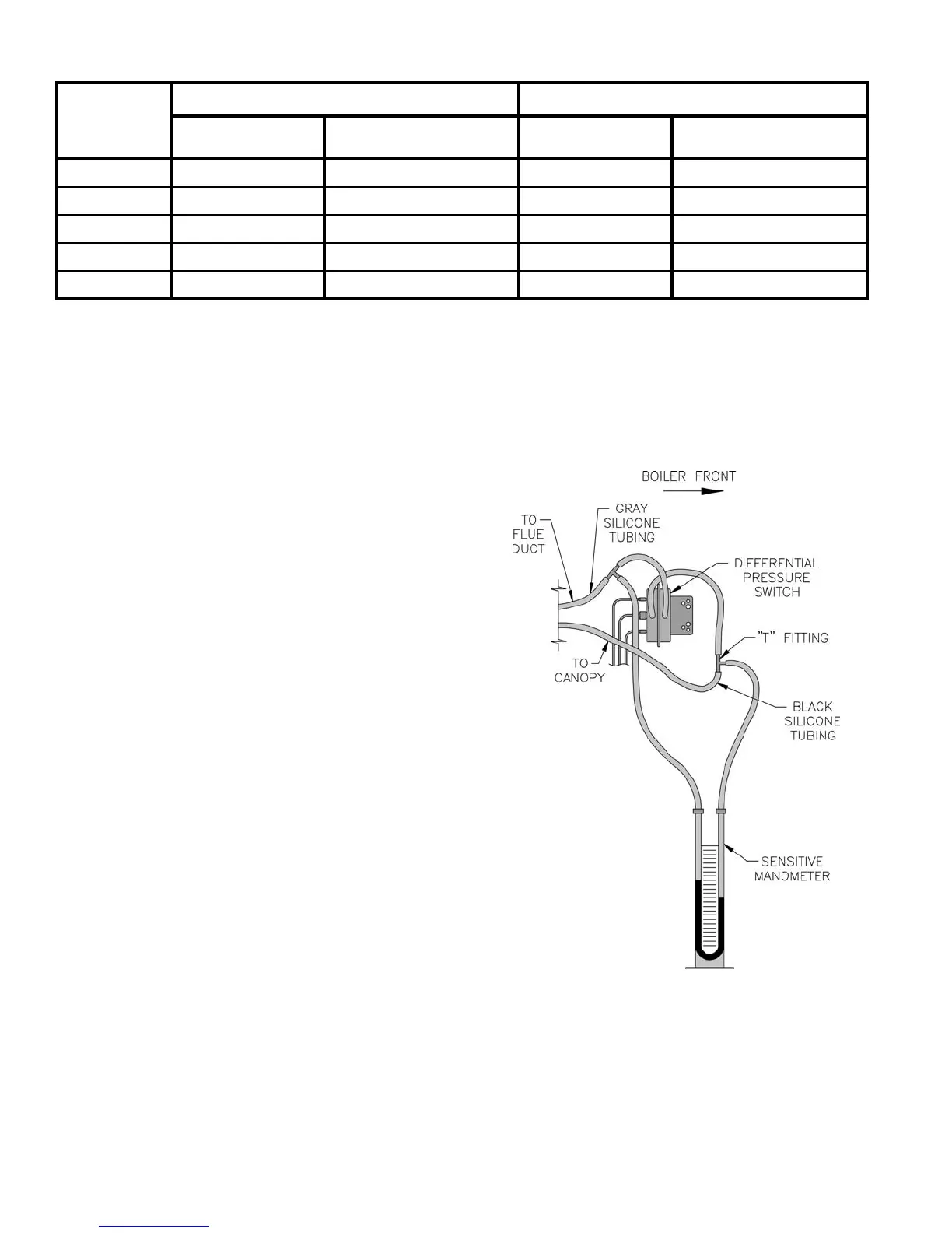
G. Procedure for measuring differential pressure, (see
Figure 54).
1. With boiler off, remove Gray and Black Hoses at
differential pressure switch.
Figure 54: Differential Pressure Measurement
2. With tees and ¼ inch aluminum stubs, connect water
manometer as shown with additional tubing.
3. Start boiler and read Pressure on Manometer when
boiler water temperature reaches operating tempera-
ture. Refer to Table 12 for minimum readings.
Boiler Model
1” Burners 40mm Burners
Main Burner with
60° Pilot Bracket
Pilot Burner Located
Between Main Burners *
Main Burner with
41° Pilot Bracket
Pilot Burner Located
Between Main Burners *
RV3 1 1 & 2 1 1 & 2
RV4 2 2 & 3 2 2 & 3
RV5 3 3 & 4 2 2 & 3
RV6 4 4 & 5 3 3 & 4
RV7 6 6 & 7 3 3 & 4
* Main burners numbered left to right as viewed from front of boiler.


 To Next Page