76
3. Pipe must be full round shape, and show no damage
from impact or excessive temperature.
4. Pipemustbesupportedatminimumve(5)foot
intervals and must not sag.
5. All vent joints must be secure and watertight.
6. All air intake joints must be secure and airtight.
Horizontal vent tee drain or vertical vent tee drain
(if used) must have minimum 6 inch trap and allow
condensate
toowfreely.ToClean:
a. Disconnectdraintubefromdraintting.
b. Flush drain tube with water. Fill trap with water.
c. Securelyfastendraintubetodraintting,
providing gas-tight and watertight seal.
7.
If pipe must be disassembled for removal of
obstructions or resealing of joint, see Section III,
Paragraphs C through E.
D. Boiler Flue Passages. Inspect for blockage or soot
accumulation.
1. Remove Main Burners. See Figure 53.
a. Remove front door.
b. Remove air intake box front door.
i. Remove sheet metal screws.
c. Disconnect pilot tubing and pilot lead wires at
the gas valve.
d. Remove wires to Flame Roll-out Switch (RV3-
RV6 only).
e. Remove Burner Access Panel.
f. Mark location of Main Burner with Pilot Bracket
on gas manifold.
g. Hold Main Burner on throat. Lift front of
burnerstoclearorice.Burnerwhichholdspilot
can be removed by lifting the burner adjacent to
itsrightrst.
2. Remove Jacket Top Rear Panel.
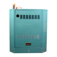
3. Disconnect Black Silicone Tubing from Canopy.
4. Remove Canopy Assembly.
a. Loosen carriage bolts.
b. Pry canopy from boiler sections.
5. RemoveFlueGasBafes.InspectFlueGasBafes
for deterioration.
6. Inspectuepassages.Cleanwithuebrush.See
Figure 53.
7. Inspect heating surface in combustion chamber.
Clean with straight handle wire brush.
8. InstallFlueGasBafes.
9. Replace Canopy Assembly and seal.
10. Connect Silicone Tubing between Pressure Fittings
on Canopy Assembly and Pressure Switch. Route
through bushings in Vestibule Panel . See Figure
51.
1
1. Install Jacket Top Rear Panel.
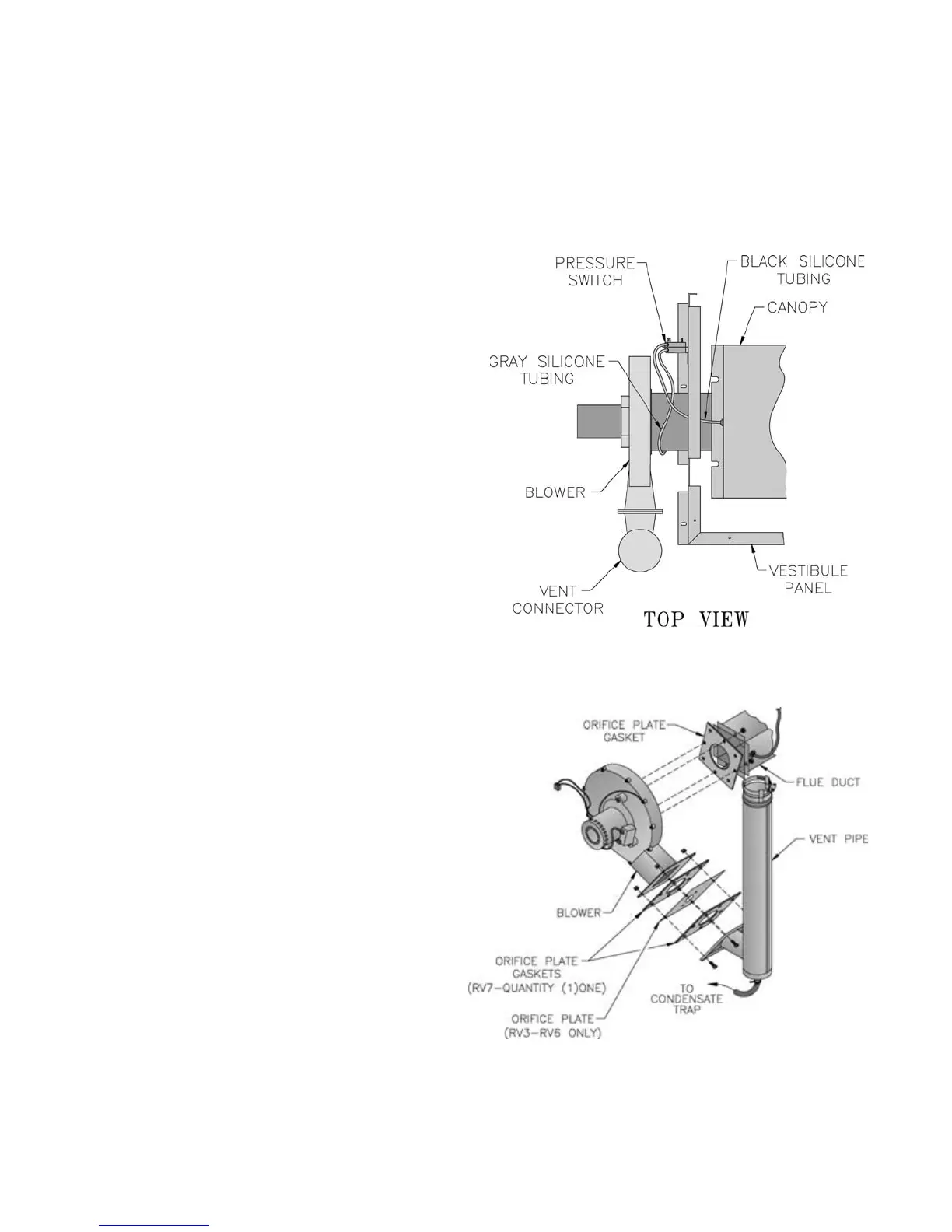
12. Connect vent system. See Figure 52.
13. Ensureoriceplateandnewtwo(2)gasketsarein
place. See Figure 52.
Figure 51: Silicone Tubing Assembly
Figure 5
2: Blower Vent Connector Assembly