22
f. Drive nipples squarely into section using
block of wood and hammer, or preferably, an
aluminum head hammer. (Burnham oers a
Polyethylene Block for setting the nipples, part
number 8052601). Place block over entire nipple
edge and hit the wood with the hammer.
Nipples must be driven in evenly and to the proper
depth to assure tight joints. Most nipple leaks are
caused by tilted or cocked nipples.
DO NOT use steel/iron head hammer to drive
nipples without using a wood block. Nipple
damage may result.
Les mamelons doivent être enfoncés
uniformément et à la bonne profondeur pour
assurer des joints serrés. La plupart des fuites
de mamelons sont causées par des mamelons
inclinés ou armés.
NE PAS utiliser de marteau à tête en acier / fer
pour enfoncer les mamelons sans utiliser de cale
en bois. Des dommages au mamelon peuvent en
résulter.
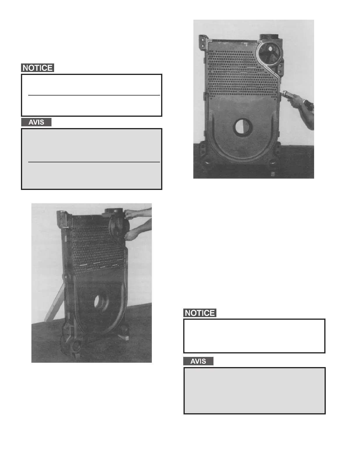
Figure 6: Setting of Nipples
h. Remove a 96″ length of berglass rope from
the assembly carton. Starting with the area
around the upper 7″ nipple port, rmly press
the rope into the groove, so that the adhesive
holds it in place. (If more than 25 minutes have
passed since the adhesive was applied, it may
be necessary to reapply.) Continue to ax the
rope to the groove in this fashion around the
perimeter of the section. Make sure that the rope
does not droop or hang outside of the groove.
When the end of the groove is reached, cut o
the excess rope. Push the length of excess rope
into the groove at the top corner of the section
face (opposite of the 7″ nipple port.) Cut o and
discard any remaining rope after groove is lled.
See Figure 7.
The sections must be assembled according to the
arrangement shown to ensure proper operation, proper
assembly of canopy, jacket and alignment of piping and
tankless heaters with jacket knockouts. Start with the
back section and work towards the front.
Les sections doivent être assemblées selon
la disposition illustrée pour assurer un bon
fonctionnement, un assemblage adéquat de l’auvent,
de la chemise et l’alignement de la tuyauterie et des
appareils de chauage sans réservoir avec des
débouchures de chemise. Commencez par la partie
arrière et travaillez vers l’avant.
Figure 7: Axing the Fiberglass Rope
g. A special nipple setting gauge is provided for the
nipples. Gauge nipple at 90° angles to insure that
it is driven to the proper depth into the nipple
opening (nipple port). Cut-out in gauge must rest
on nipple, with legs of gauge touching nished
face of section, when nipple is properly driven.
See Figure 6.
 Loading...