23
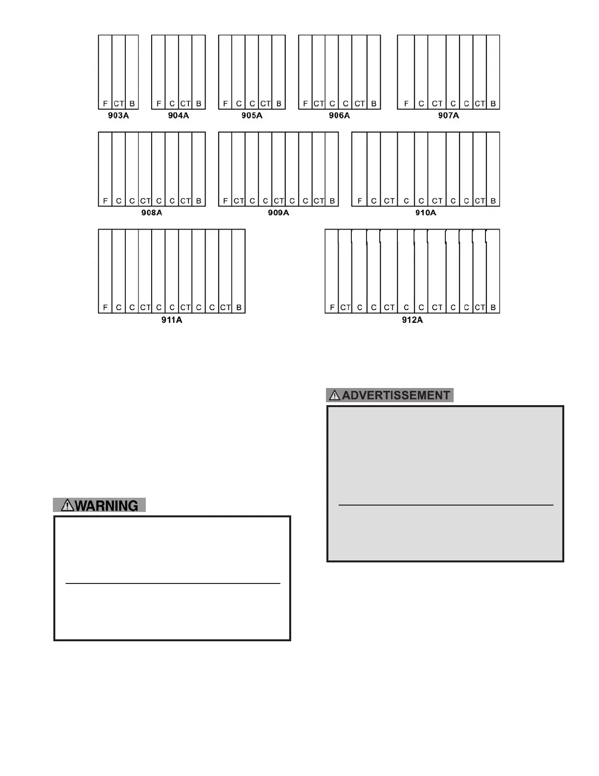
Figure 8: V9A Section Arrangement
i. From the “Section Arrangement” chart, select
the next section according to the “Identication
Code” at the top of the chart. See Figure 8. Use
a wire brush to clean the groove in the face
of the next section. Then, using a cartridge of
RTV 6500 or RTV 736 sealant in a caulking gun,
ll the groove in this section with silastic sealant.
Touch-up any missed spots before draw-up.
Touch-up after draw-up has no value.
Sections must be drawn-up tight immediately after
properly applying sealant for best results. Although
sections may be joined within two (2) hours of
applying sealant, humidity and temperature aect
cure time. If a “thick skin” has been formed on the
sealant bead, remove and re-apply sealant.
Sealant must be properly applied to ALL
boiler joints. Failure to properly seal the boiler
joints will result in combustion gas leaks through
the joint. DO NOT operate boiler with combustion
gas leaks.
Les sections doivent être étirées de manière
étanche immédiatement après avoir correctement
appliqué le scellant pour de meilleurs résultats.
Bien que les sections puissent être jointes dans les
deux (2) heures suivant l’application du scellant,
l’humidité et la température aectent le temps de
durcissement. Si une «peau épaisse» s’est formée
sur le cordon de scellant, retirez et appliquez de
nouveau le scellant.
joints de chaudière. Le fait de ne pas sceller
correctement les joints de la chaudière entraînera
des fuites de gaz de combustion à travers le joint.
NE PAS faire fonctionner la chaudière avec des
fuites de gaz de combustion.
j. Clean and lubricate nipple ports on next section
to be assembled and place on nipples previously
installed in rear section. To facilitate assembly,
it is advisable to enter the upper nipple rst in
its port. Then enter the lower nipples in their
respective ports. If necessary, place a lifting bar
(crowbar) under the center of the section and lift
the nipple port onto the upper nipple.
k. Drive sections in place with a heavy block of
wood, striking blows as squarely as possible over
nipple port.
NOTES: FOR BOILERS LESS TANKLESS HEATER, REPLACE THE "CT" SECTIONS WITH "C" SECTIONS. TANKLESS
SECTIONS: IF BOILER CAN TAKE MULTIPLE TANKLESS COILS, BUT NOT ALL TANKLESS COILS WILL
BE USED, INSTALL COILS TOWARDS BACK OF BOILER, FOLLOWING SECTION ARRANGEMENT CHART.
 Loading...