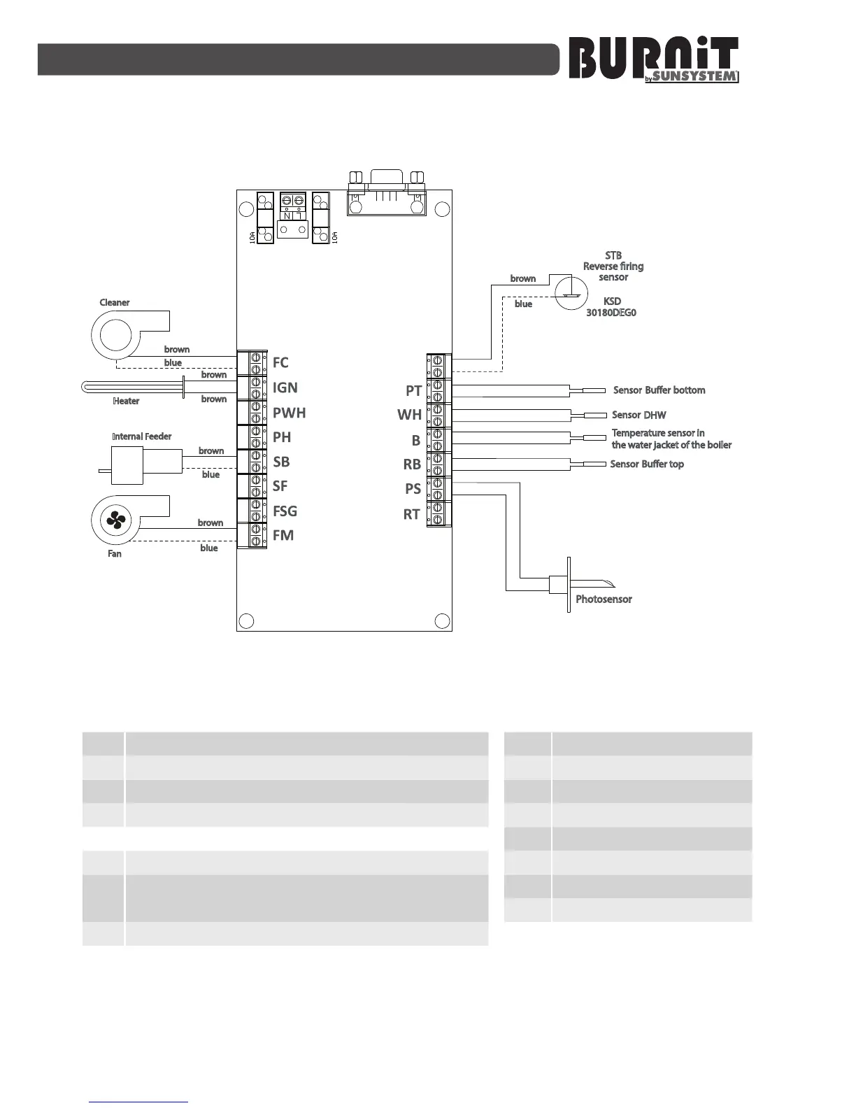
Diagram 6.
Wiring diagram of connecon of internal devices / sensors to the burner
KSD
30180DEG0
С
NPBC V3M -2
OD
Cleaner
brown
brown
brown
Heater
blue
brown
blue
brown
brown
Fan
Photosensor
STB
Reverse ring
sensor
Buer bottom
Sensor
DHW
Sensor
Buer top
Sensor
Temperature sensor in
the water jacket of the boiler
Internal Feeder
blue
blue
Inputs
Group1
RT Room thermostat
PS Photo sensor
RB Temperature sensor at the top of the buffer
B Boiler temperaure sensor
Group2
WH DHW Sensor
PT
Temperature sensor at the bottom of
the buffer
OD Sensor reverse burning
Outputs
FM Fan main
FSG Fan smoke gases
SF Screw fuel
SB Screw burner
PH Pump heang
PWH Pump water heater
IGN Igniter
FC Fan cleaning