3 | Product description
0870S03226_VRD 2072-3108_-0000_IM_en
9 /
3.4 Function principle
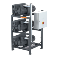
3.4.1 Vacuum system VRD
The switch and control cabinet is installed on the vacuum system. The rotary vane vacu-
um pumps are activated with soft-starters to avoid excessive mains loads. When
switched on, the first rotary vane vacuum pump starts immediately, the other rotary
vane vacuum pumps are switched on one after the other with a time offset of 10 s.
Gas delivery is effected by the one-stage rotary vane vacuum pumps. Pressure gas is ex-
hausted against the atmosphere.
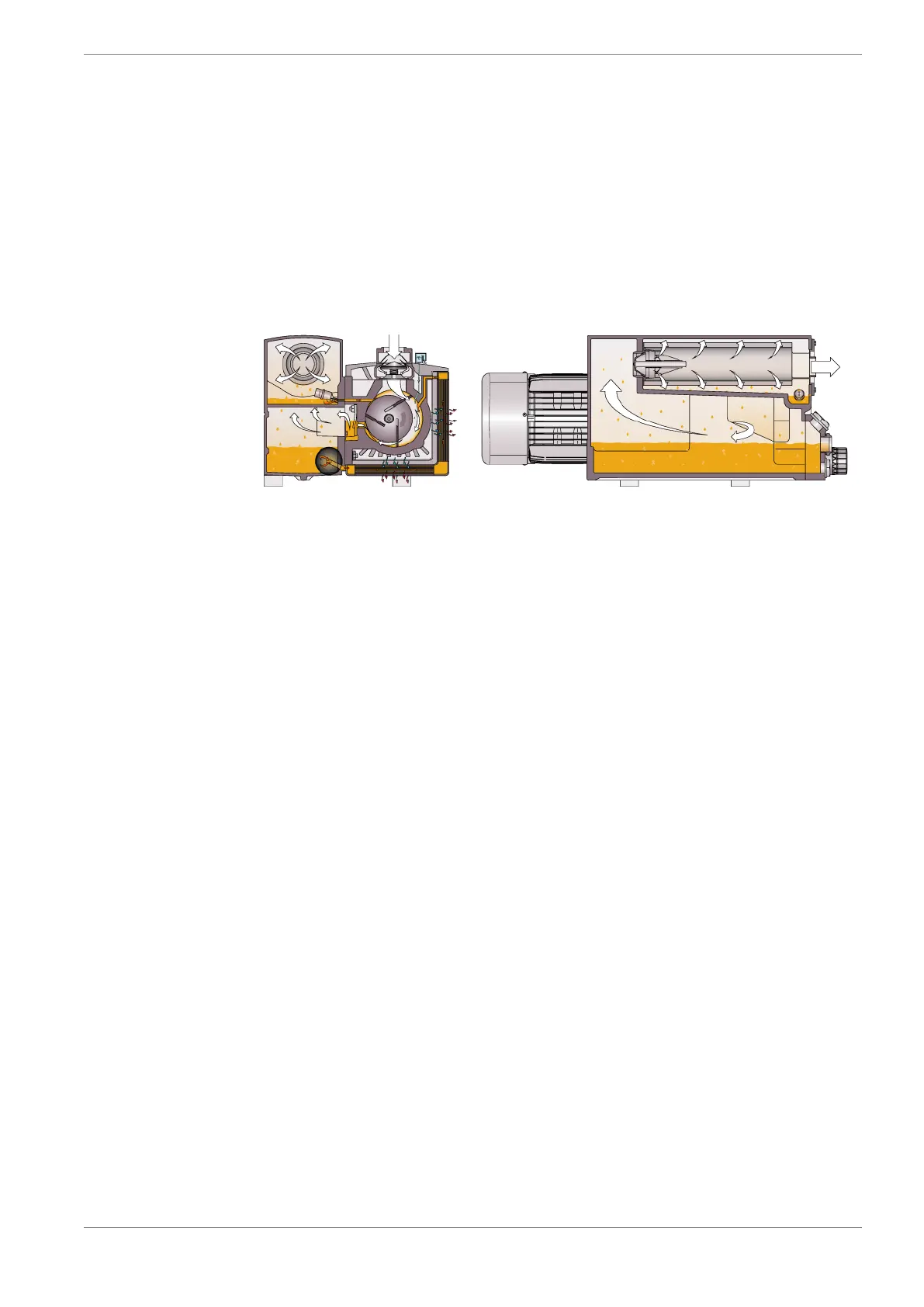
3.4.2 Rotary vane vacuum pump R5 RD
Fig. 3 : Operating principle of the rotary vane vacuum pump R5 RD
The vacuum pump R5 RD works according to the rotary vane principle.
The oil seals the spaces, lubricates the sliders and discharges the compression heat. The
oil filter cleans the circulating oil.
Then the exhaust filters separate the oil from the discharged gas.
3.4.3 Gas ballast valve
The vacuum pumps are equipped with a gas ballast valve. The gas ballast valve is used
for the addition of a limited quantity of ambient air to the process gas, to counteract the
condensation of vapor in the vacuum pump. The gas ballast valve reduces the final pres-
sure of the vacuum pump, see “Technical data” in chap. 15.
3.5 Intended use
The vacuum system was designed for conveying air and other dry, non-aggressive, non-
toxic and non-explosive gases.
Conveying any other media leads to increased thermal and/or mechanical stress of the
vacuum system and is only permitted in coordination with Busch.
The vacuum system is designed for operation in a non-hazardous area. The vacuum sys-
tem can be operated continuously at final pressure and is suitable for continuous opera-
tion at up to 100 mbar. The permitted ambiance conditions can be found in the technical
data (chap. 15).
The vacuum system is designed for indoor use; for outdoor installation, contact Busch to
make special arrangements if necessary.