14 | Connection values of the vacuum system VRD
/ 44
0870S03226_VRD 2072-3108_-
14 Connection values of the vacuum system VRD
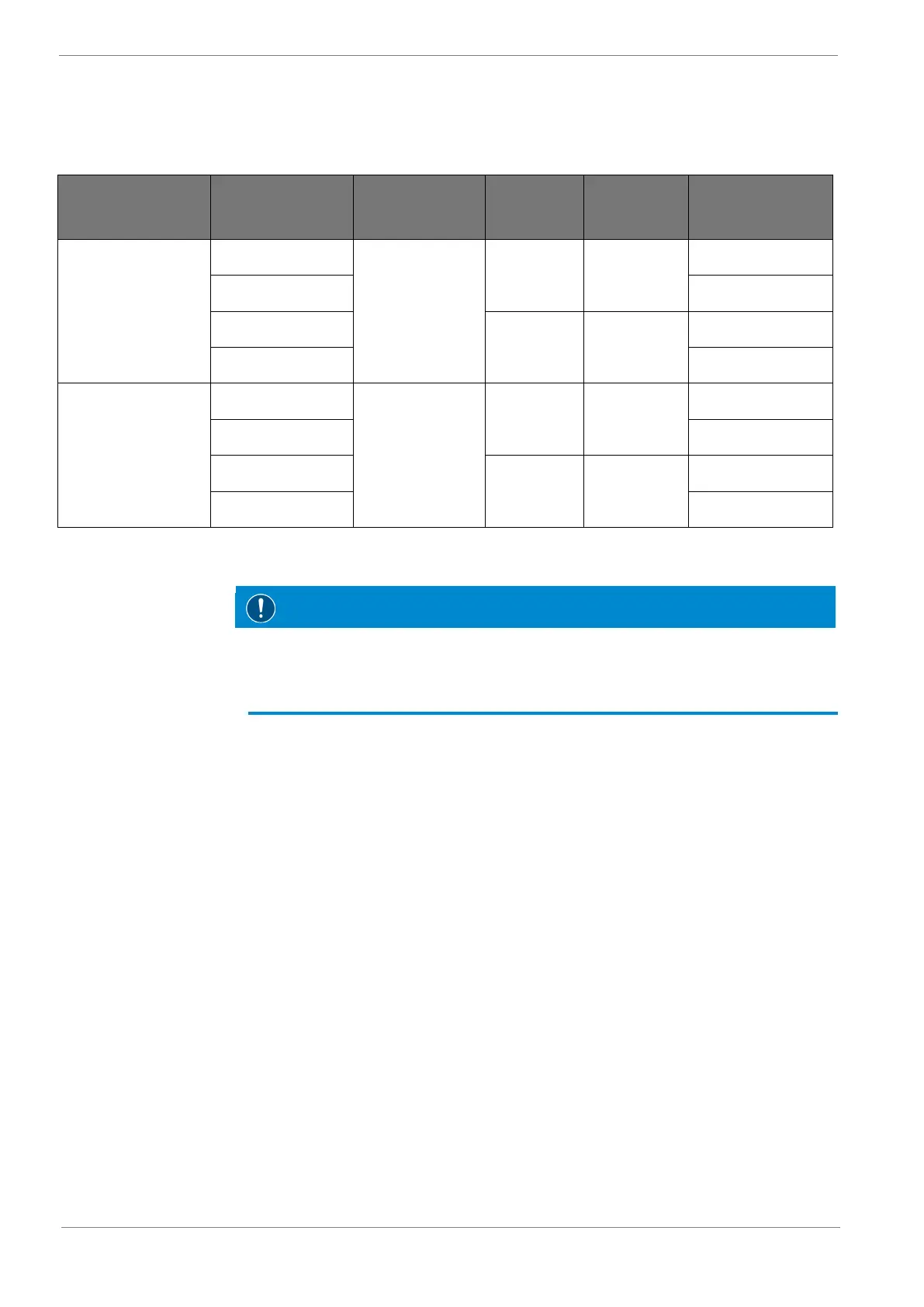
14.1 Connection values
Vacuum system
type
Voltage Control voltage Frequency
Power con-
sumption
Max. permissible
pre-fuse
VRD 2072
190 – 230 V*
24 VDC
50 Hz 11.0 kW
80 A
380 – 400 V 50 A
200 – 230 V*
60 Hz 13.2 kW
80 A
400 – 480 V 50 A
VRD 3108
190 – 230 V*
24 VDC
50 Hz 16.5 kW
125 A
380 – 400 V 63 A
200 – 230 V*
60 Hz 19.8 kW
125 A
400 – 480 V 63 A
Tab. 6: Connecting values of the vacuum systems VRD
Damage to the drives.
• *Before commissioning, check the motor circuits (double star / triangle) in the motor
terminal board of the rotary vane vacuum pumps, see circuit diagram in the switch
and control cabinet.
14.2 Signal exchange
The following signals are available to the user (see circuit diagram in the switch and con-
trol cabinet):
• Status message of the vacuum system in operation – potential-free message
• Status message vacuum system failure – potential-free message
• External signal – vacuum system ON / OFF