EasyManuals Logo

BWT AQA total 2500 User Manual

BWT AQA total 2500
To Next Page IconTo Next Page
To Previous Page IconTo Previous Page
Page #23 background imageLoading...
Page #23 background image
20
GB
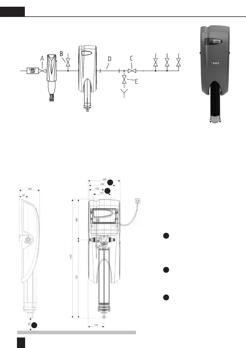
5.3. Installation diagrams
a.) Installation diagram AQA total 1500
A Water counter shut-off valve
B Outlet valve to garden
C Unit shut-off valve
D Test section
E Rinsing valve
The test section is an easily removable, new pipe section, which should have a pipe length/pipe diameter of
approximately 6:1. It must be tted immediately downstream of the AQA total system.
Installation length without
glands (5/4“ locking nut, 5/4“
external thread)
Installation length with glands
(both sides 1“ external thread)
Necessary space for removal of
working unit
1
1
2
2
3
3

Table of Contents

Other manuals for BWT AQA total 2500

Questions and Answers:

Question and Answer IconNeed help?

Do you have a question about the BWT AQA total 2500 and is the answer not in the manual?

BWT AQA total 2500 Specifications

General IconGeneral
BrandBWT
ModelAQA total 2500
CategoryWater Filtration Systems
LanguageEnglish

Related product manuals