20 20
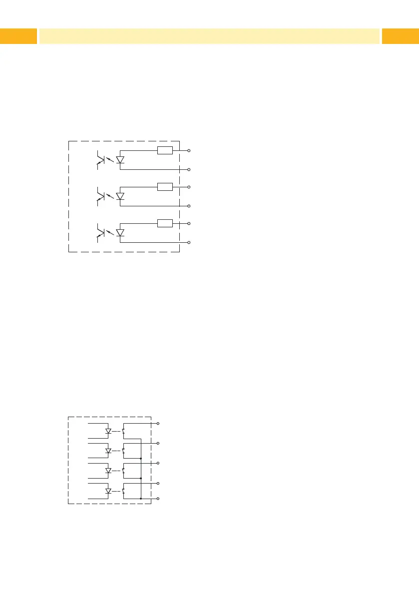
6.3 Internal Circuit of the Inputs
The inputs XSTART, XFEH and XETE are designed for an operating voltage
of 24 V.
For each signal X
(input) exists a separate reverse line RX(input) at the
connector.
For that the following signal pairs result:
Pin 1 - XSTART
Pin 9 - RXSTART
Pin 2 - XFEH
Pin10 - RXFEH
Pin 3 - XETE PS5 only
Pin11 - RXETE PS5 only
Figure 17 Internal circuit of the inputs
Input STA (Pin 13) must be connected to GND (Pin 12) to enable the signal
XSTART.
6.4 Internal Circuit of the Outputs
For the outputs solid-state relays are used. The outputs have the common
reference potential RUEL (Pin 14).
Switching the outputs is realized by opening or closing a contact between
RUEL and the respective output.
U
max
= 42 V I
max
= 100 mA
Pin 4 - XESP
Pin 5 - XEDG
Pin 6 - XDNB
Pin 7 - XEDST
Pin 14 - RUEL
Figure 18 Internal circuit of the outputs
6 Peripheral Interface