EasyManuals Logo

CAB SQUIX Service Manual

CAB SQUIX
28 pages
To Next Page IconTo Next Page
To Previous Page IconTo Previous Page
Page #15 background imageLoading...
Page #15 background image
15
2 Replacing Assembly Units
2.8 Installing the PCB I/O Interface
Danger!
Risk of death via electric shock!
Before opening the housing cover, disconnect the device from the mains supply and wait at least one
minute until the power supply unit has discharged.
3
1
2
1
4
5
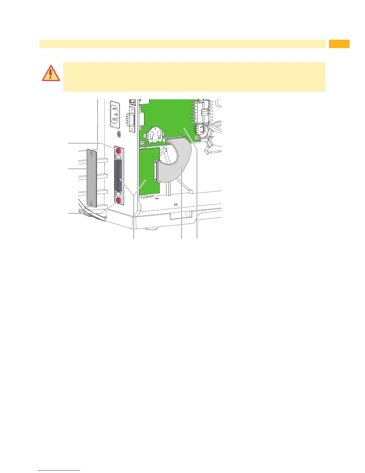
Fig. 10 Installing the PCB I/O interface
1. Unplug the printer from the electrical outlet.
2. Remove the rear cover.
3. Loosen two screws (1)and remove cover (2).
4. Insert the PCB I/O interface (3) and x it with two screws (1)
5. Connect the cable (4) to the PCB I/O interface (3) and the PCB CPU (5).
6. Mount the rear cover.

Other manuals for CAB SQUIX

Questions and Answers:

Question and Answer IconNeed help?

Do you have a question about the CAB SQUIX and is the answer not in the manual?

CAB SQUIX Specifications

General IconGeneral
Print TechnologyThermal Transfer / Direct Thermal
Print Resolution300 dpi
Max Print Speed300 mm/s
DisplayLCD
InterfacesUSB, Ethernet, Serial (RS232), USB Host
Memory64 MB RAM
Media SensorsReflective, transmissive
Label Length5 to 4000 mm
KeyboardOptional
Supported MaterialsPaper, plastic, textile

Related product manuals