List of Figures
Page
vii
List of Figures
Figure 1 PMP/PTP 450 Platform Family typical bridge deployment ............................................................ 1-12
Figure 2 TDD frame division ............................................................................................................................... 1-15
Figure 3 3GHz PMP 450m Series interfaces ...................................................................................................... 2-7
Figure 4 5GHz PMP 450m Series interfaces....................................................................................................... 2-8
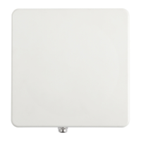
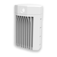
Figure 5 PMP/PTP 450i interfaces ..................................................................................................................... 2-10
Figure 6 PMP 450b Mid-Gain Series - SM interfaces ...................................................................................... 2-11
Figure 7 PMP 450b Series - SM interfaces (High Gain) .................................................................................. 2-12
Figure 8 PMP/PTP 450 Series - AP interfaces ................................................................................................. 2-13
Figure 9 PMP/PTP 450 Series – SM/BH interfaces ......................................................................................... 2-13
Figure 10 PMP/PTP 450 Series – SM/BH Connectorized interfaces ............................................................. 2-14
Figure 11 PMP 450d Series - SM Integrated Dish ............................................................................................. 2-15
Figure 12 PMP 450 Series – SM 3 GHz Integrated ........................................................................................... 2-15
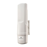
Figure 13 PTP 450 Series – BHM/BHS ............................................................................................................... 2-15
Figure 14 AP/BHM diagnostic LEDs, viewed from unit front ......................................................................... 2-17
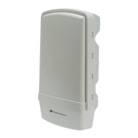
Figure 15 AP/BH diagnostic LEDs, viewed from unit front ............................................................................ 2-19
Figure 16 AC Power Injector interfaces ............................................................................................................. 2-23
Figure 17 AC+DC Enhanced Power Injector interfaces ................................................................................... 2-24
Figure 18 -48 V DC Power Injector interfaces .................................................................................................. 2-26
Figure 19 -20 to 32 VDC Power Injector interfaces ......................................................................................... 2-27
Figure 20 Gigabit Enet Capable power supply ................................................................................................ 2-29
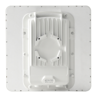
Figure 21 PMP 450m Series - AP rear interfaces ............................................................................................. 2-31
Figure 22 PMP 450m 3GHz - AP rear interfaces ............................................................................................. 2-32
Figure 23 PMP/PTP 450i Series - ODU rear interfaces ................................................................................... 2-33
Figure 24 PMP/PTP 450i Series – Connectorized ODU antenna interfaces................................................ 2-34
Figure 25 PMP/PTP 450b Mid-Gain SM - ODU rear interfaces...................................................................... 2-35
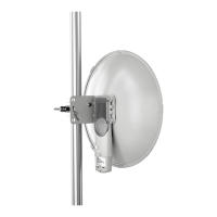
Figure 26 PMP/PTP 450b High Gain SM - ODU rear interfaces .................................................................... 2-36
Figure 27 Outdoor drop cable ............................................................................................................................ 2-38
Figure 28 Optical SFP transceiver module ...................................................................................................... 2-40
Figure 29 Long cable gland ............................................................................................................................... 2-40
Figure 30 Alignment Tone Cable ....................................................................................................................... 2-42
Figure 31 RJ12 Alignment Tone Cable ............................................................................................................... 2-42
Figure 32 Cable gland (part number #N000065L033) ................................................................................. 2-44
Figure 33 Cable grounding kit ............................................................................................................................ 2-49
Figure 34 UGPS ..................................................................................................................................................... 2-52
Figure 35 Cluster Management: Scenario 1 ....................................................................................................... 2-54
Figure 36 Cluster Management: Scenario 2 ...................................................................................................... 2-55
Figure 37 Controller Module ............................................................................................................................... 2-55
Figure 38 Injector Module ................................................................................................................................... 2-56
Figure 39 CMM4 (Rack Mount) .......................................................................................................................... 2-58
Figure 40 CMM4 56 V power adapter (dongle) .............................................................................................. 2-59
Figure 41 CMM4 power adapter cabling diagram ........................................................................................... 2-59
Figure 42 CMM4 (Cabinet with switch) ............................................................................................................ 2-61
Figure 43 CMM3 .................................................................................................................................................... 2-63
 Loading...