F
M
A B GND
A B
S1 GND
10 11 E 524 0
M N
+ E -
FC FA F
10 TS 2 CX CY
1 2 3P 7
AF
R700
R800
10 11 E 5
24 0
M N
+ E -
FC FA F
10 TS 2 CX CY
1 2 3P 7
AF
R700
R800
A B GND
A B
S1 GND
10 11 E 5
24 0
M N
+ E -
FC FA F
10 TS 2 CX CY
1 2 3P 7
AF
R700
R800
-
+
-
+
p. 15 - Manual FA01719-EN - 03/2022 - © CAME S.p.A. - Translated original instructions
Green
Red
Orange
White
Red
Orange
Encoder
Gate open signaling output
(Contact rated for: 24 V AC/DC - 3 W max.).
See function F 10.
Either flashing light or cycle light connection output
(Contact rated for: 24 V AC/DC - 25 W max.).
See function F 18.
24 V AC/DC - max 40 W accessories power-supply output
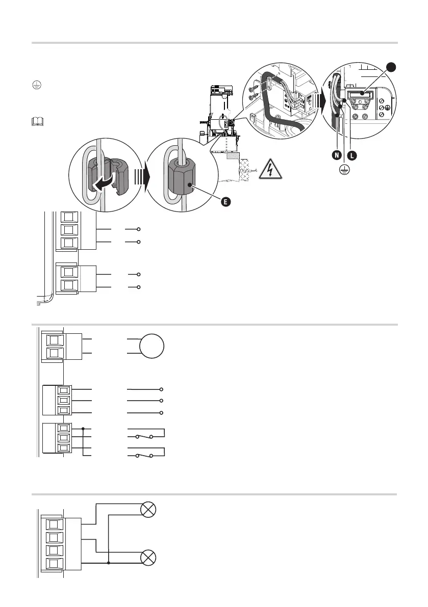
24 V AC/DC control board power-supply input
120 / 230 V AC - 50/60 Hz
Closing limit-switch (NC contact)
Opening limit-switch (NC contact)
FACTORY WIRING
Green
Brown
White
24 V DC gearmotor
SIGNALING DEVICES
INPUT VOLTAGE
Line fuse
🅛 Phase
🅝 Neutral
Earth
🅔 Ferrite
Apply the ferrite supplied to the power supply cable.
The cable must pass through the ferrite twice
(2 turns).
 Loading...