Pag. 11 - Manual code: 119AV31 ver. 2.0 09/2010 © CAME cancelli automatici s.p.a. - The data and information reported in this installation manual are susceptible to change at any time and without obligation on CAME cancelli automatici s.p.a. to notify users.
6.1 Adjusting the brake microswitches
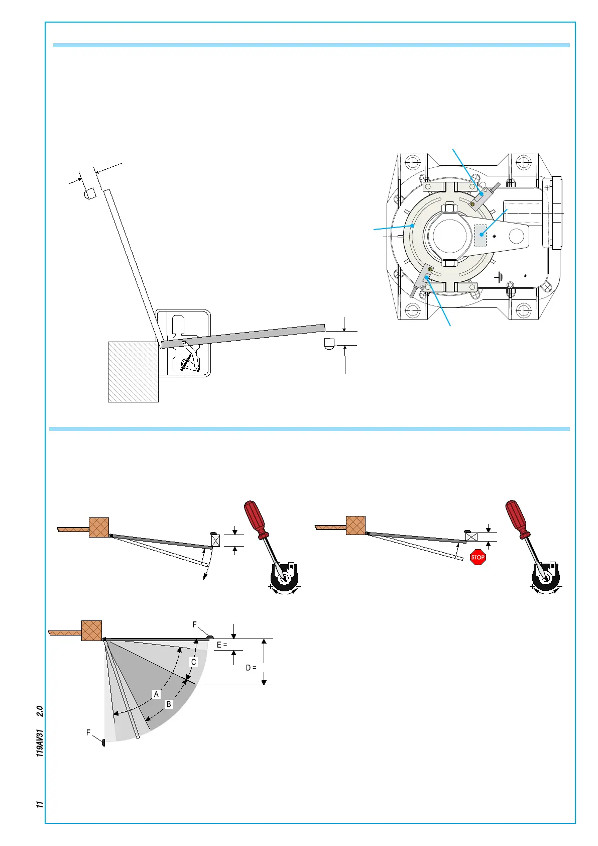
Fig. 7
– Using the motor, make so that the gate leaf is max 20 inches from being fully opened. At this point do a rst adjustment of
the (endstop) microswitches, positioning them close to the magnet. Consider that this type of endstop reads the magnetic
eld. You may have to repeat the procedure to increase the precision of the adjustment (g. 6/7)
1.2” in
2.4” in
6.2 Adjusting the limit stop’s stopping zone
Prepare a 2 x1 inch template and hold it up against one of the two mechanical stops as shown in g. 8 (adjustment is to be
made either on the closing endstop or opening endstop). Activate the gate - either using a command button or the remote
control - and turn the OP TIME (TL) trimmer clockwise until the gate leaf inverts its direction just as it touches the obstacle/
template. Then turn the template from its short side (g. 9) and check that the gate leaf stops against the obstable/template.
Otherwise activate the trimmer clockwise.
Fig. 8
Fig. 9
A =Eective range of the motion-inverter amperometric sensor.
B =Run zone at normal speed.
C =Run zone at slow speed.
D =Eective range of the motion-stop amperometric sensor
E =Opening/Closing position mechanical gate stops
2” in
20” in
Microswitch
Endstop
holding plate
Magnet
Microswitch
20” in.
20” in.

 Loading...


