Pag. 10 - Manual code: 119AV31 ver. 2.0 09/2010 © CAME cancelli automatici s.p.a. - The data and information reported in this installation manual are susceptible to change at any time and without obligation on CAME cancelli automatici s.p.a. to notify users.
5.7 Manual release
- In emergencies (i.e. power outages) the release mechanisms allow the gate to hook back up when closing.
- You may choose among three dierent release models: model A4366 with customised key (Fig. 5-A), model A4365 with
tri-lobed key and model A4364 with lever key (Fig. 5-B). We suggest greasing the release’s hook-up key (Fig. 5-B – part. 3)
consult the documentation pertinent to the relative items for the release procedure.
Note: Release operations need to be carried out during emergency procedures and with the power disconnected.
3
Fig. 5
Fig. 5-A
Fig. 5-B
A4366
A4364
A4365
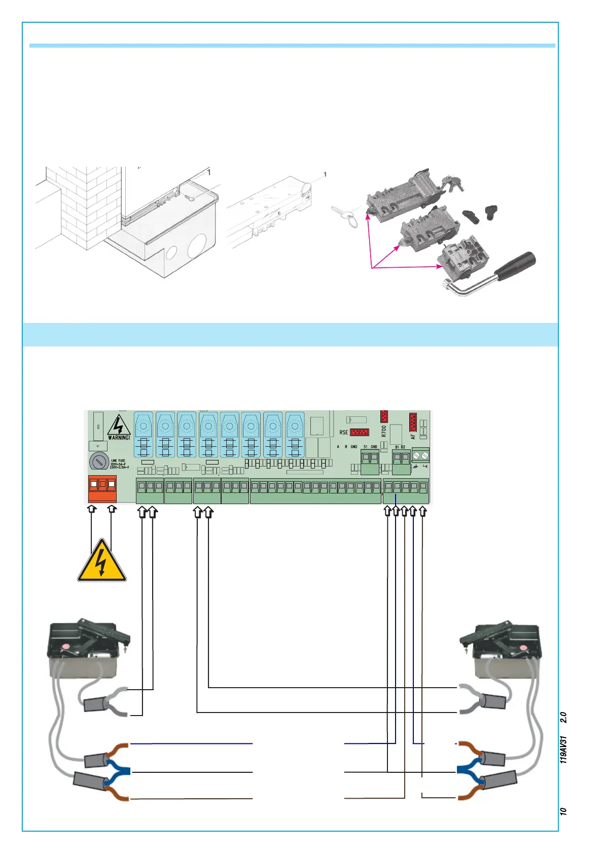
- We suggest making the gearmotor cable connections in shunt boxes;
For further information concerning the functions, see the technical documentation for the ZLJ24U control panel.
6 Connecting to the control panel
ZLJ24U Control panel
26V
0V
17V
0
230V
26V
0V
17V
0
230V
L2TL1T L2TL1T
24 12 0 24 12 0
L N
E
+ -
E 10 11 TS E ES 1 2 3 4 5 CX CY
B1 B2S1
CZ7 2
FA2
GND
FC2FA1 FC1
+ -
M1 M2N1 N2
ENC1 ENC2
Connecting the 24V d.c. delayed closing gearmotor
120 V a.c.
power supply
BLUE
BLUE/BROWN
BROWN
Connecting the 24V d.c. delayed opening gearmotor
BLUE
BROWN

 Loading...


