Pag. 8 - Manual code: 119AV31 ver. 2.0 09/2010 © CAME cancelli automatici s.p.a. - The data and information reported in this installation manual are susceptible to change at any time and without obligation on CAME cancelli automatici s.p.a. to notify users.
8
6
5
2
4
7
10
9
3
1
1
10
3
4x1,5
3x1,5
120V
4x1
2x1,5
RG58
3x1
5x1
2x1
4x1
RX
TX
RX
TX
4x1,5
2x1
11
Note: If the cable length differs from that specified in the table, then you must determine the proper cable diameter in the
basis of the actual power draw by the connected devices and according to the local electrical code standards.
For connections that require several, sequential loads, the sizes given on the table must be re-evaluated based on actual
power draw and distances. When connecting products that are not described in this manual, please refer to the
instructions that come with said products.
5.3 Cable list and minimum thickness
Connections Type of cable
Length of cable 3 < 32ft Leng. cable 32 < 65ft Leng. cable 65 < 100ft
Control panel power supply 230V
UL LISTED
CABLE/WIRE
3G x 14AWG 3G x 14AWG 3G x 14AWG
Motor power supply 24V
3 x 20AWG 3 x 20AWG 3 x 20AWG
Flashing light
2 x 20AWG 2 x 20AWG 2 x 20AWG
Photocell transmitters
2 x 20AWG 2 x 20AWG 2 x 20AWG
Photocell receivers
4 x 18AWG 4 x 18AWG 4 x 18AWG
Accessories power supply
2 x 20AWG 2 x 20AWG 2 x 20AWG
Control and safety devices
2 x 20AWG 2 x 20AWG 2 x 20AWG
Antenna connection RG58
max. 32 ft
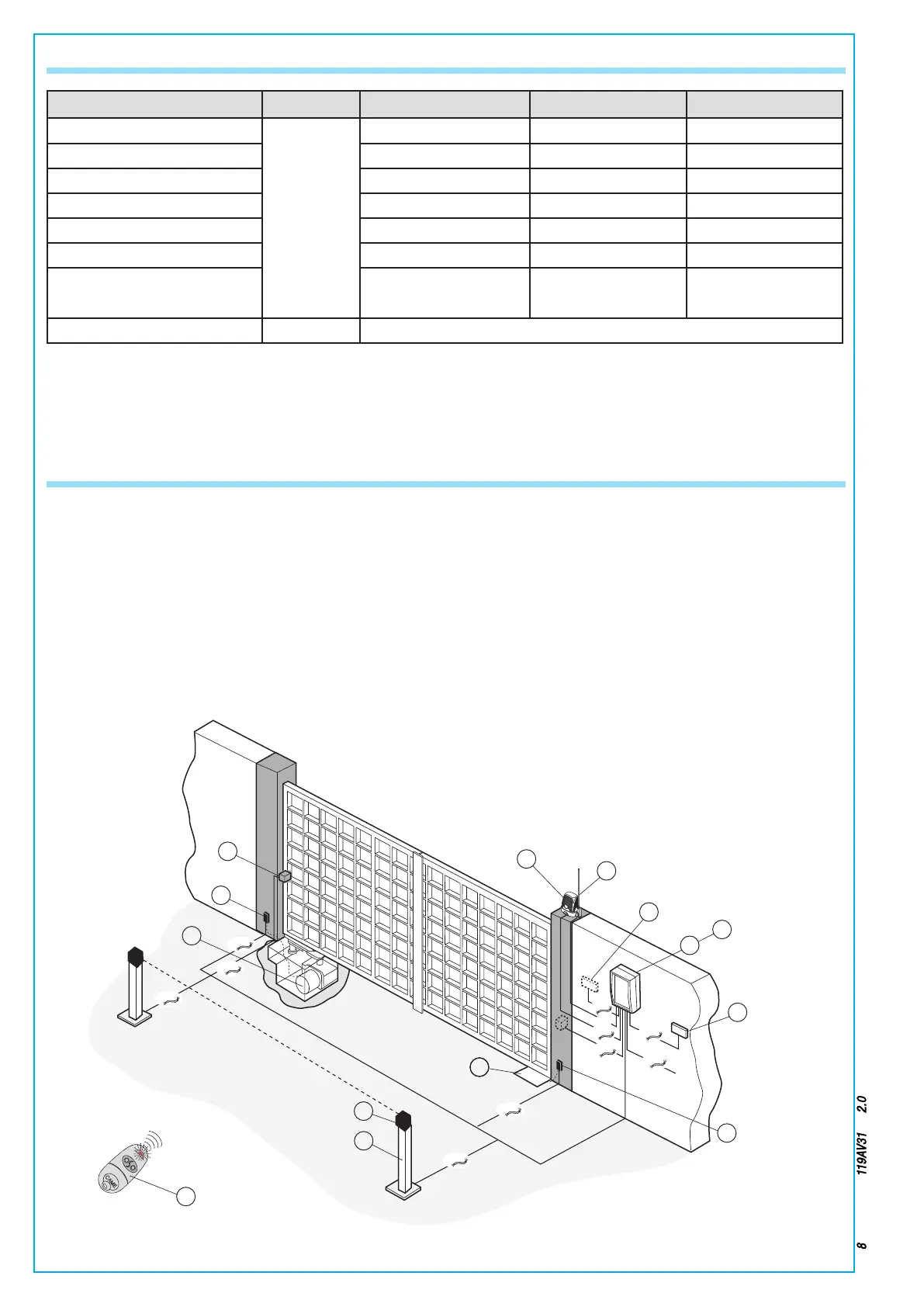
1) FROG unit
2) Control panel
3) Safety photocells
4) Radio receiver
5) Key-switch selector
6) Antenna
7) Command push-buthon panel
8) Flashing light
9) Photocell column
10) Shunt box
11) Transmitter
5.4 Standard installation

 Loading...


