~1°
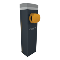
~89°
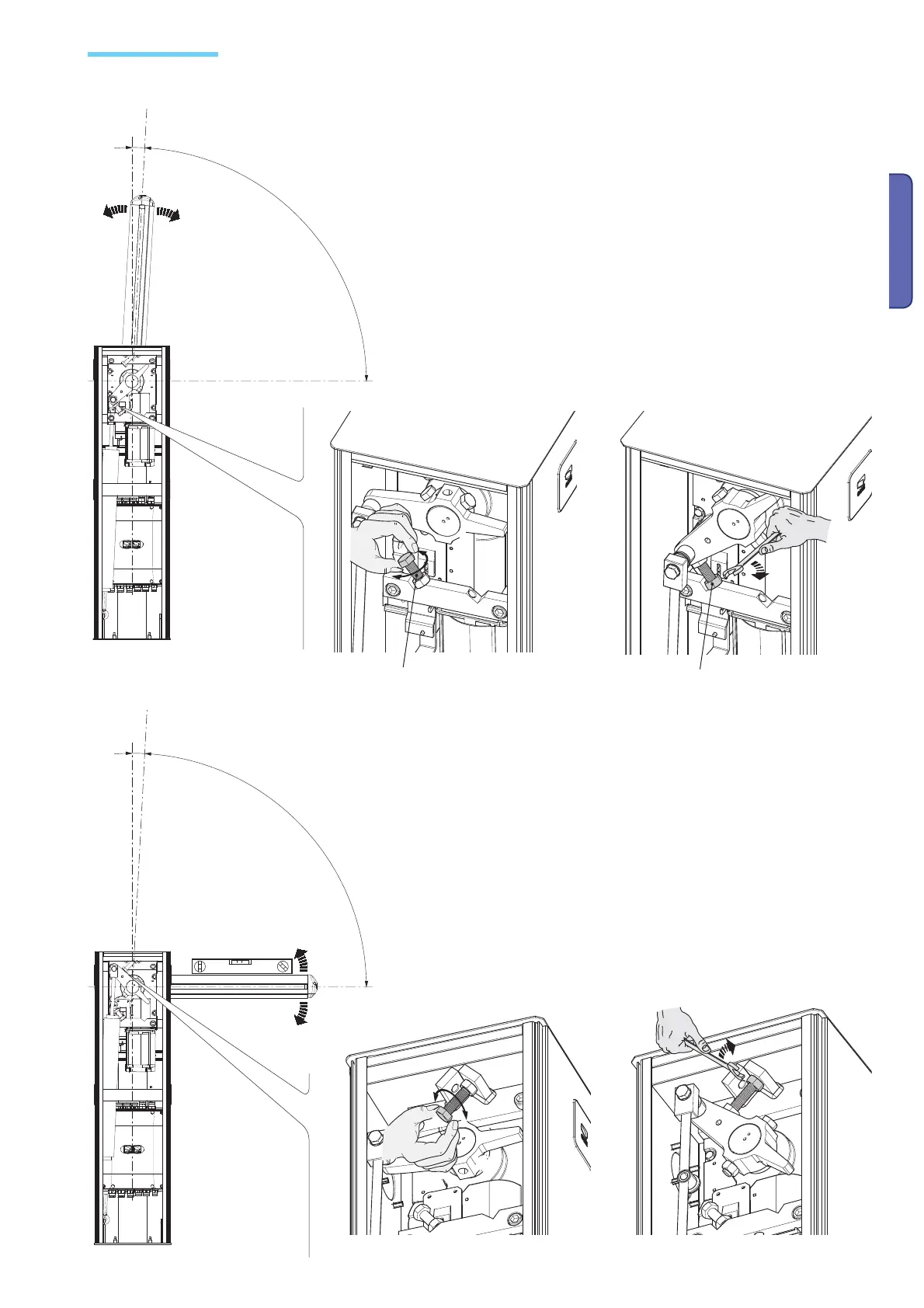
~1°
~89°
p.
15 - Manual Code:
119GV18ver.
1.1 12/2011 © CAME Cancelli Automatici S.p.a. - The data and information in this manual may be changed at any time and without obligation on the part of Came Cancelli Automatici S.p.a. to notify said changes.
ENGLISH
N.B.: to do after electrical connections are made to the control panel.
Close the inspection door and power up the system.Activate the arm to check whether it is parallel to the
road surface when close and at about 89° when open.
To correct the vertical position (=opening), lower the barrier arm, open the
inspection door and rutn the opening mechanical stop either clockwise or
counterclockwise, then secure the stop with the counter nut.
To correct the horizontal position (=closing), raise the bar, adjust the mechanical
closing stop and secure it with the counter nut.
Adjusting endpoints
Mechanical stop counter nut

 Loading...