1
2
p.
9 - Manual Code:
119GV18ver.
1.1 12/2011 © CAME Cancelli Automatici S.p.a. - The data and information in this manual may be changed at any time and without obligation on the part of Came Cancelli Automatici S.p.a. to notify said changes.
ENGLISH
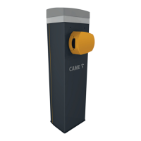
Insert the customised key into the lock
and turn it counterclockwise.Remove the
inspection door from the cabinet.
Position the cabinet to the anchoring base
and secure it using the washers and nuts.
N.B.: install the cabinet with the
inspection door facing an easily
accessible direction.
Warning:the barrier must be mounted by at least two persons.Use proper hoisting equipment when transporting the barrier.
During mounting phase, the barrier may be unstable.Do rest against barrier until fully mounted, to avoid any tumbling over.
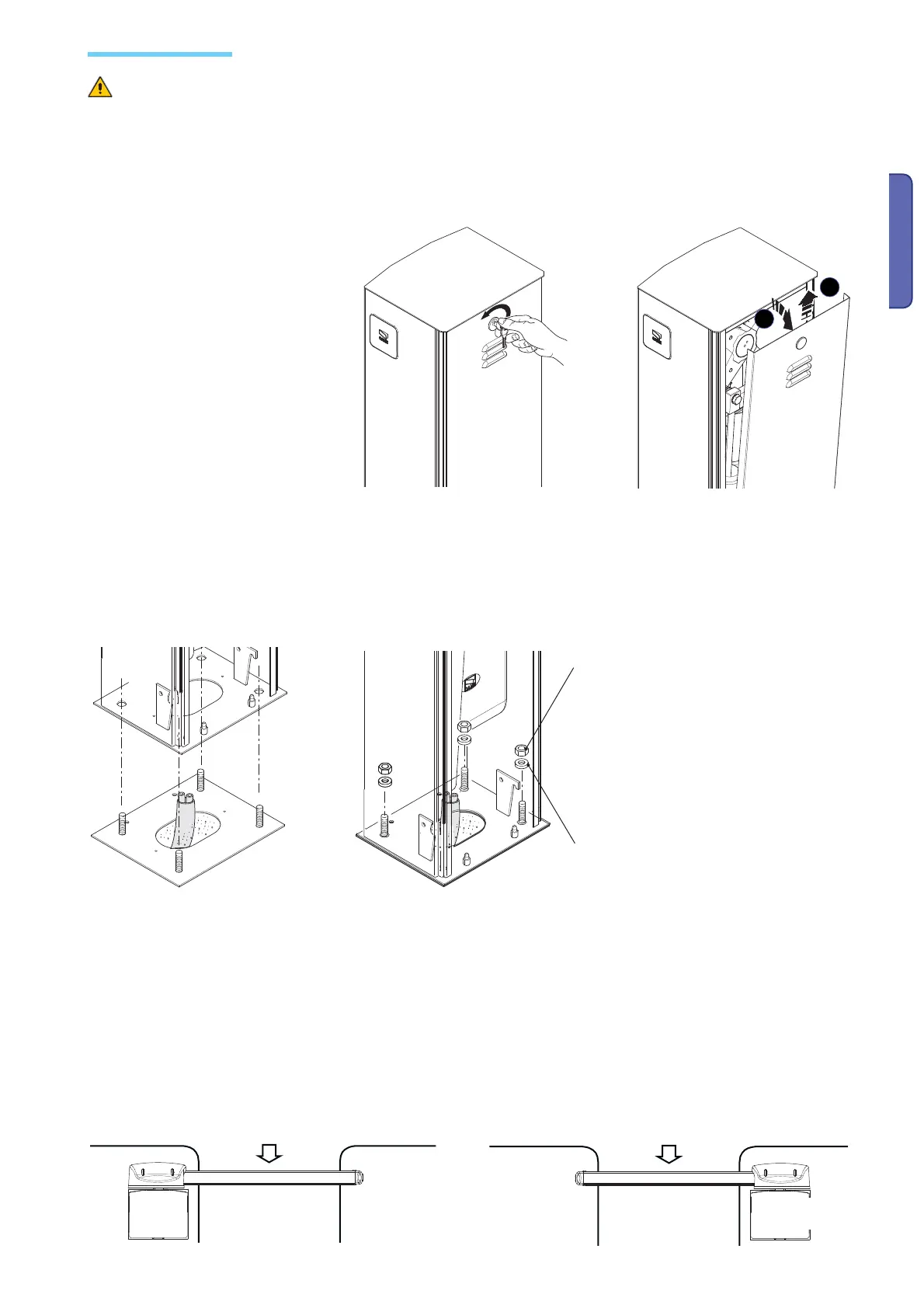
To change rotation at a later date, request documentation from authorised dealer or directly contact the Came office near you (see
last page or www.came.com)
Left barrier
RIGHT barri-
er
Entrace
Internal zone
Entrance
Internal zone
Installing the operator
M12 UNI 5588 nut
Washer

 Loading...