CAME
1
5
11
7
9
4
3
12
10
8
6
2
6
p.
7 - Manual Code:
119GV18ver.
1.1 12/2011 © CAME Cancelli Automatici S.p.a. - The data and information in this manual may be changed at any time and without obligation on the part of Came Cancelli Automatici S.p.a. to notify said changes.
ENGLISH
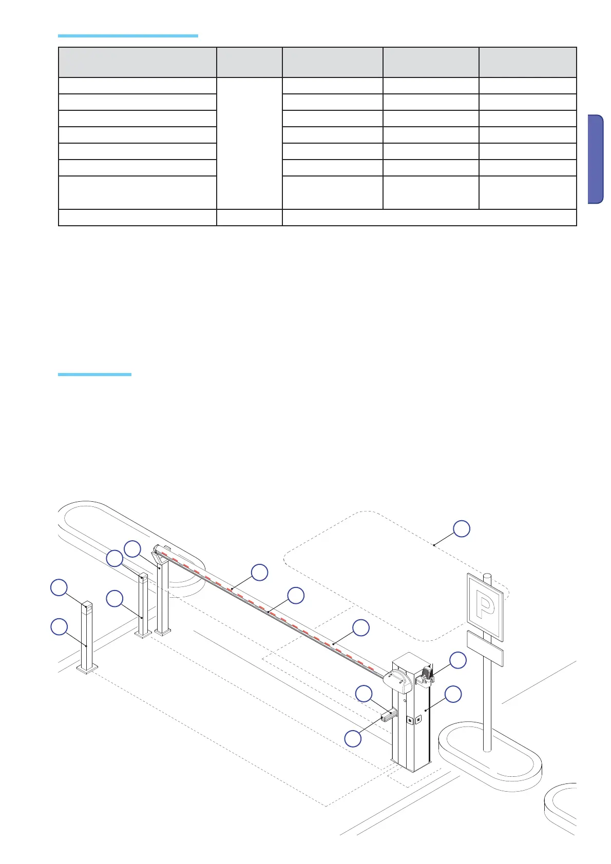
1. Barriers 001G3250
2. Flashing light
3. Semi elliptical rod
4. Luminous cord
5. Red reflective strips
6. RX photocells
Installation: Type
Types of cables and thicknesses
N.B.:. If cables are of a different length than that shown in the table, determine the cable section based on the actual draw and the number
of connected devices and according the what is set forth in the CEI EN 60204-1 code of regualtions.
For connections featuring several loads on the same line (i.e. sequential ones), the dimensions shown on the table must be reconsidered
according to the total draw and actual distances. When connecting products not featured in this manual, only refer to the literature ac-
companying such products.
7. Support for photocells
8. Small post for photocells
9. Fixed support
10. Command device (i.e. keyboard, magnetic key, transponder, etc.)
11. Stand for command device
12. Metal mass detector
Connection Cable type
Cable length
1 < 10 m
Cable length
10 < 20 10 ÷ 20 m
Cable length
20 < 30 20 ÷ 30 m
230 V power source to control panel
FROR CEI
20-22
CEI EN
50267-2-1
3G x 1.5 mm
2
3G x 1.5 mm
2
3G x 2.5 mm
2
Motor power supply (V) 24 V 3G x 1.5 mm
2
3G x 1.5 mm
2
3G x 2.5 mm
2
Flashing light 2 x 1.5 mm
2
2 x 1.5 mm
2
2 x 1.5 mm
2
TX photocells 2 0.5 x 1.5 0.5 mm
2
2 x 0.5 mm
2
2 0.5 x 1.5 0.5 mm
2
RX photocells 4 x 1.5 0.5 mm
2
4 x 1.5 0.5 mm
2
4 x 1.5 0.5 mm
2
Accessories power source 2 0.5 x 1.5 0.5 mm
2
2 0.5 x 1.5 0.5 mm
2
2 x 1 mm
2
Safety and command devices 2 0.5 x 1.5 0.5 mm
2
2 0.5 x 1.5 0.5 mm
2
2 0.5 x 1.5 0.5 mm
2
RG58 Antenna max. 10 < 10 m

 Loading...