RX
TX
⑤
⑥
⑧
⑦
④
③
①
⑥
Page 10 - Manual FA01799 -EN - 04/2022 - © Came S.p.A. - The contents of this manual may be changed, at any time, and without notice. - Translation of the original instructions
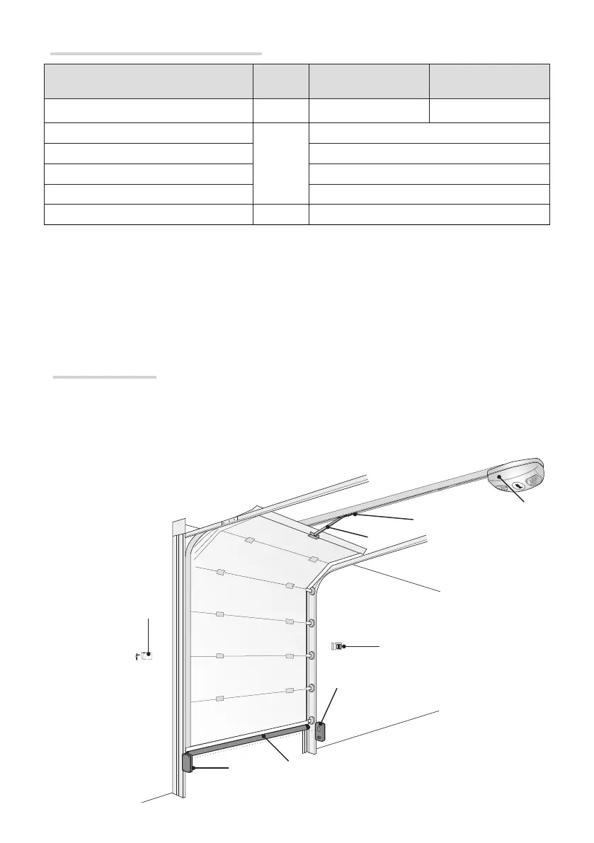
Standard installation
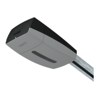
① Operator with receiver
② Slide guide
③ Release device
④ Transmission arm
⑤ Key-switch selector
⑥ Photocells
⑦ Keypad
⑧ Sensitive safety-edge
Cable types and minimum thicknesses
Connection Cable type
Cable length
1 < 15 m
Cable length
15 < 30 m
Control panel power supply 230 V AC H05VV-F 3G x 1.5 mm
2
3G x 2.5 mm
2
Flashing light
FROR CEI
20-22
CEI EN
50267-2-1
2 x 0.5 mm
2
Photocell transmitters 2 x 0.5 mm
2
Photocell receivers 4 x 0.5 mm
2
Command and safety device 2 x 0.5 mm
2
Antenna RG58 max 10 m
If cable lengths differ from those specified in the table, establish the cable sections depending on the actual
power draw of the connected devices and according to the provisions of regulation CEI EN 60204-1.
For multiple, sequential loads along the same line, the dimensions on the table need to be recalculated according
to the actual power draw and distances. For connecting products that are not contemplated in this manual, see
the literature accompanying said products
Page 10 - Manual FA01799 -EN - 04/2022 - © Came S.p.A. - The contents of this manual may be changed, at any time, and without notice. - Original instructions