EasyManua.ls Logo

CAME VER - User Manual

CAME VER
24 pages
Print Icon
To Next Page IconTo Next Page
Loading...
1
Documentazione
Tecnica
35
rev. 3.3
01/2001
©
CAME
CANCELLI
AUTOMATICI
119E35
VER
CANCELLI AUTOMATICI
1. Gruppo VER
2. Quadro comando
incorporato
Accessori
3. Ricevitore radio
4. Pulsantiera da
interno
5. Fotocellule di
sicurezza
6. Costola a raggi
infrarossi
7. Braccio adattatore
8. Dispositivo di
sblocco
9. Lampeggiatore
10. Antenna
11. Selettore a chiave
1. VER unit
2. Incorporated control
panel
Accessories
3. Radio receiver
4. Internal pushbutton
array
5. Safety photocells
6. Infrared rib
7. Adaptor arm
8. Release mechanism
9. Flashing light
10. Antenna
11. Key-operated selector
switch
1. Groupe VER
2. Armoire de
commande
incorporée
Accessoires
3. Récepteur radio
4. Poussoirs internes
5. Photocellules de
sécurité
6. Profil de sécurité à
rajons infrarouges
7. Bras adaptateur
8. Dispositif de
déblocage
9. Clignotant
10. Antenne
11. Sélecteur à clé
1. VER-Antriebsmotor
2. Intergrierte
motorsteuerung
Zubehör
3. Funkempfänger
4. Schalteinheit für
Innenmontage
5. Lichtschanken
6. Infrarot
Sicherheitsleiste
7. Adapterarm
8. Entriegelungssjstem
9. Blinkleuche
10. Antenne
11. Schlüsselschalter
1. Conjunto VER
2. Cuadro de
mando
incorporado
Accesorios
3. Radiorreceptor
4. Botonera interior
5. Fotocélulas de
seguridad
6. Protector por
infrarrojos
7. Brazo adaptador
8. Dispositivo de
desbloqueo
9. Lámpara intermitente
10. Antena
11. Selector a llave
Automazione con sistema a traino per porte basculanti e sezionali
Automatic traction system for overhead and sectional doors
Automatisme avec sistéme "a traction" pour portes basculantes et sectionnels
Schubantriebssistem für Schwing-und Sektionaltore
Automatización con sistema "por arrastre" para puertas basculantes y seccionales
Impianti tipo -
Standard installations -
Installation type
- Standard Montage -
Instalaciòn tipo
Question and Answer IconNeed help?

Do you have a question about the CAME VER and is the answer not in the manual?

CAME VER Specifications

General IconGeneral
BrandCAME
ModelVER
CategoryGate Opener
LanguageEnglish

Summary

VER Automatic Traction System Overview

System Components Identification

Lists and identifies the key components of the VER automatic traction system.

General Specifications and Operating Limits

General System Specifications

Details design compliance, warranty, and general features of the automation system.

Operating Limits for Door Types

Specifies the types and dimensions of doors compatible with the gearmotors.

Technical Description and Dimensions

Motor and Control Unit Description

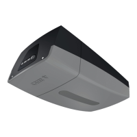
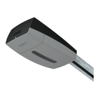
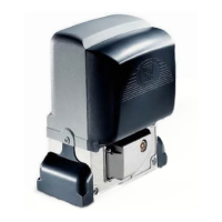
Provides a detailed technical overview of the motor, gearbox, and integrated control panel.

External Dimensions Diagram

Illustrates the overall physical dimensions of the unit for installation planning.

Accessories and Application Examples

Optional Accessories for Installation

Information on optional accessories for specific door types and installation adaptations.

Typical Installation Examples

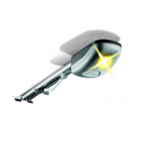
Visual examples of how the system is applied to different door types.

Unit Assembly Instructions

Step-by-Step Assembly Guide

Detailed instructions for assembling the automation unit, including chain and guides.

ZL54 Control Board Technical Description

Connectable Accessories

Lists accessories compatible with the ZL54 control board, such as battery backup.

Selectable Functions

Details on functions configurable via DIP-switches, including auto-closing and safety.

Control Board Adjustments

Explanation of trimmer settings for automatic closing time, slowdown, and sensitivity.

Control Board Function Selection

DIP-Switch Configuration

Guide to configuring control board functions using the DIP-switch settings.

Electrical Connections

Wiring Terminal Layout

Diagram showing terminal assignments for power, motor, accessories, and limit switches.

Photocell Connection Polarity

Critical note on maintaining correct polarity when connecting photocells (TX and RX).

Radio Control Installation and Encoding

Installing the AF Card

Procedure for inserting the AF radiofrequency card into the motherboard.

Transmitter Encoding Procedure

Step-by-step guide to register transmitters by encoding their codes onto the control board.

Limit Switch Adjustment

Adjusting Opening Limit Switches

Instructions for setting the door's fully open position using cams and microswitches.

Adjusting Closing Limit Switches

Instructions for setting the door's fully closed position, including slowdown.

Periodic Maintenance

Maintenance Recommendations

Guidelines for regular lubrication of guide wheels and checking chain tension.

Related product manuals