Pag.
-
manual code
319S33EN ver.
06/2015
© CAME S.p.A.- The data and information in this manual may be changed at any time and without obligation on the part of CAME S.p.A. to notify said changes.
Respect cable distances and diameters as shown in the "Cable tyeps and sections" table.
The overall power load of the connected motor must not exceed 600 W.
4 Description
2.1 Intended use
Legend of symbols
2 Intended use and settings
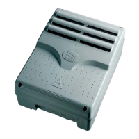
The ZC3 control panel is engineered to command industrial sliding gate operators of the C-BX and F4000 series, 230 V powered.
Every installation and use other than that specified in this manual is forbidden.
3 Reference standards
"IMPORTANT INSTALLATION SAFETY INSTRUCTIONS"
“WARNING: Improper installation may result in serious harm. Please follow all installation instructions”
“This manual is intended only for professional installers or other competent individuals”
2.2 Application settings
CAME S.p.A.employs an ISO 9001 certified quality management system and an ISO 14001 environmental management system.
Came entirely engineers and manufactures in Italy.
This product is subjected to the following regulations: see statement of compliance.
Engineered and built entirely by CAME S.p.A.
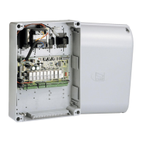
The control panel is powered by 230 v AC on terminals L1 and L2
with max frequency of 50/60 Hz.
The command devices and accessories are powered by 24 V.
Warning!The accessories must not exceed 20 W overall.
All connections are protected by quick fuses, see table.
The card provides and controls the following functions:
- automatic closing after an opening command;
- partial opening for pedestrian passage;
- obstacle detections when gate is not moving at any point;
- “manual opening”;
- Pre-flashing movement indicator;
- adjusting the connected automated device's torque;
- Running the safety test function.
The available command modes are:
- opening/closing;
-opening/closing with maintained action;
- Partial opening;
- total stop.
The photocells, after detecting an obstacle, may trigger:
- the reopening of the closing gate;
- the reclosing of the opening gate;
- a partial stop;
- a total stop.
Special trimmers regulate:
- the working time for automatic closing;
- the working time;
- the partial opening time.
You can also connect:
- gate open warning-lamp;
- fixed time courtesy-lamp lighting the parking area;
- courtesy -lamp lighting the parking area for opening/closing
cycle.
This symbol shows parts which must be read with care.
This symbol means the parts descibe safety issues.
This symbol tells you what to tell the user.
FUSE TABLE
to protect: fuses for:
Electronic board (line) Two 5 A fuses
Command devices (control unit) 630 mA
Accessories 1 A
TECHNICAL DATA
line voltage 230 V - 50/60 Hz
maximum allowed power load 600 W
power draw when idle 60 mA
maximum power for 24 V
accessories
20 W
circuit insulation class
container material ABS
container protection rating IP54
temperatura di esercizio -20 + 55 °C
 Loading...