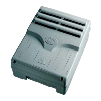
240 mm
120 mm
145 mm
320 mm
215 mm
295 mm
(mm)
L1T L2T VS
CT
24 12
0
L1 L2 U
VWEE1EX
10 11 TS 1 2
3
7
3P 4 5
2C1CXFCFA
F
B1 B2
ON
11 12 13 14 15 16 17 18 19 20
ON
12345678910
234
01224
1
L1T
L2T
VS
FUSE
ACCESS.
315mA
LINE FUSE 5A
+ AUT.CL. - + PAR.OP. -
+ OPER.TIME -
AF
CONTROL BOARD
ZC3
CH1 CH2
CLOSE OPEN
1 2 3 4 5 6 7 8 9 10 11 12
V1 V2 V3 V4 V5
04 05 06 07 08
CONTROL BOARD
1A
FUSE
1
2
13
5 6
12
7 8
10
11
4
3
9
Pag.
-
manual code
319S33EN ver.
06/2015
© CAME S.p.A.- The data and information in this manual may be changed at any time and without obligation on the part of CAME S.p.A. to notify said changes.
4.1 Dimensions, centre distances and anchoring holes
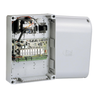
8.2 main components
Warning! Before acting on the eqipment,
cut off the main power supply and disconnect
the emergency batteries (if present).
Connect the black wires protruding from
the card onto condenser connectors.
1 Connecting terminals
2 5 A line fuse
3 1 A accessories fuse
4 24 V power on LED warning light
5 Working time adjuster trimmer
6 Automatic closing time adjuster trimmer
7 Partial opening adjusting trimmer
8 LED warning light
9 Code memorising buttons
10 Functions selector (see p. 9)
11 Radio frequency card socket (see table)
12 Motor torque limiter (see p. 9)
13 630 ma card fuse
 Loading...