25
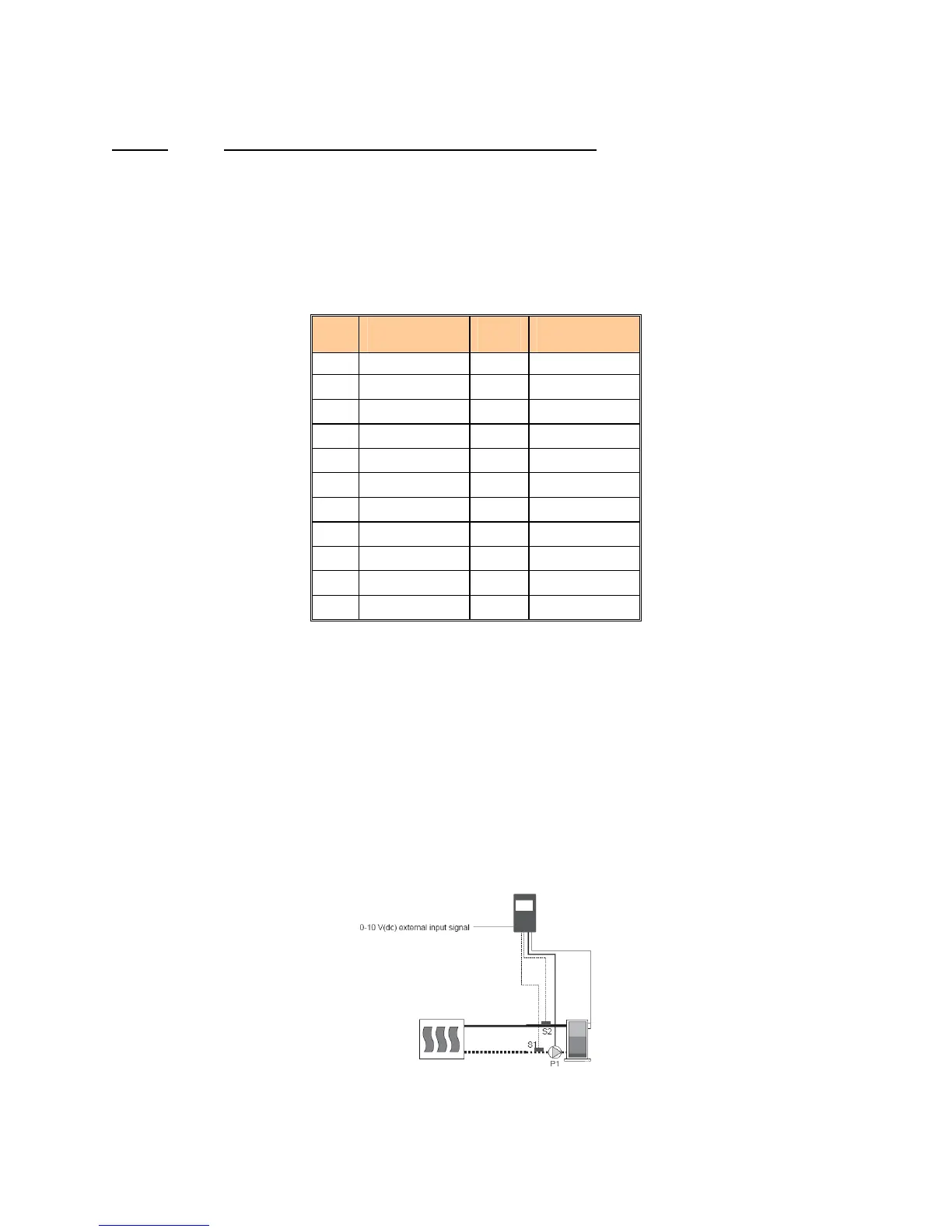
Mode 6: External Target Temperature using Boiler Inlet Sensor
The external input signal can be provided from a BMS, EMS or a tekmar tN4 System Control. The
external input signal creates an internal demand and changes the boiler target according to a linear scale.
The BTC 1 modulates the boiler to maintain the boiler target at the inlet sensor.
An internal heat demand is generated when an analog positive 2-10VDC signal is applied to the +V input
and a negative DC signal is applied to the Com/- input.
The following table shows the various signals required to generate various Target temperatures.
Table 7: External Signal Cross Reference Chart
4-20
mA
Boiler
Target
0-10V
(dc)*
Boiler
Target
0 - - - (OFF) 0 - - - (OFF)
2 - - - (OFF) 1 50
o
F (10
o
C)
4 50
o
F (10
o
C) 2 68
o
F (20
o
C)
6 70
o
F (21
o
C) 3 86
o
F (30
o
C)
8 90
o
F (32
o
C) 4 103
o
F (39
o
C)
10 110
o
F (43
o
C) 5 121
o
F (49
o
C)
12 130
o
F (54
o
C) 6 139
o
F (59
o
C)
14 150
o
F (66
o
C) 7 157
o
F (69
o
C)
16 170
o
F (77
o
C) 8 174
o
F (79
o
C)
18 190
o
F (88
o
C) 9 192
o
F (89
o
C)
20 210
o
F (99
o
C) 10 210
o
F (99
o
C)
* requires 500Ω resistor
A 4-20mA signal can be converted to a 2-10VDC signal by installing a 500Ω resistor on the external input
signal device’s terminal.
If the inlet sensor is ½ (half) of the differential below the Boiler Target, the BTC 1 then changes the
proportional modulation output to the START modulation setting, the Stage contact (pins 15 & 16) closes
to proceed to trial for ignition. The burner remains at minimum modulation until the flame is proved and
then the modulating output changes the boiler burner output to maintain the programmed boiler target
temperature at the inlet sensor. If the inlet sensor reaches ½ (half) of the differential above Boiler Target,
the burner shuts off. Once the external heat demand is removed, the BTC 1 turns off the appliance and
operates the boiler pump based on the PUMP DELAY setting.
The auto re-set limit is set to 210°F and is fixed. In addition to the auto reset limit the factory installs a
manual re-set limit set to 250°F.
Figure 19: Mode 6 Piping Schematic