43
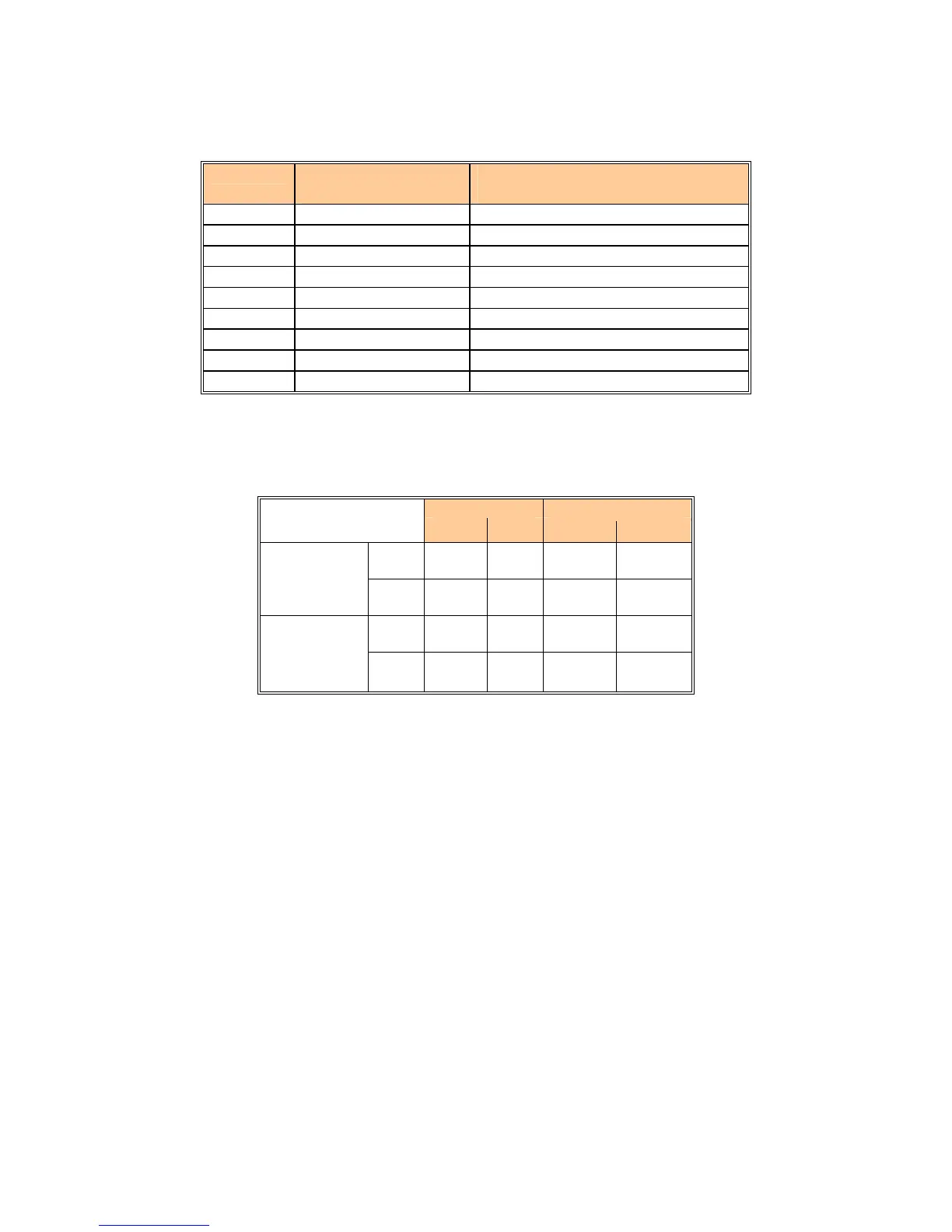
Table 9: Air Box Settings
MODEL AIR BOX “ W.C.
(with burner firing)
FLUE SWITCH RECYCLE POINT
“ W.C
060 0.20 0.15
100 0.25 0.20
150 0.30 0.25
200 0.35 0.30
250 0.38 0.33
300 0.40 0.35
400 0.80 0.70
500 0.90 0.80
600 1.00 0.90
Depending on field conditions air box pressures will have to be adjusted accordingly.
Always set the appliance for a CO
2
level in the range listed in Table 10.
Table 10: Combustion Values
Natural Gas Propane
CO
2
CO CO
2
CO
Max.
Fire
7.5% -
8.5%
< 50
PPM
9.0% -
10.0%
< 50
PPM
Non-
Condensing
Min.
Fire
7.0% -
7.5%
< 50
PPM
8.5% -
9.0%
< 50
PPM
Max.
Fire
8.5% -
9.0%
< 50
PPM
10.0% -
10.5%
< 50
PPM
Condensing
Min.
Fire
7.5% -
8.0%
< 50
PPM
9.0% -
9.5%
< 50
PPM
A qualified service technician should follow this procedure when burner needs cleaning.
1. Shut off power and close main manual gas valve.
• Allow burner to cool before removal.
2. Remove access cover screws.
• Disconnect pilot gas at bulkhead fitting.
• Disconnect ground wire and ignition wire.
• Remove two wing nuts holding down burner.
• Gently pull down and forward to disengage burner.
• Remove burner being careful to not damage the igniter or ground electrodes.
3. Thoroughly clean burner. Check all ports and air channels for blockage.
4. Reinstall the burner being careful to fully engage the back of the burner box into the retaining slot
in the combustion chamber base. Failure to properly locate the burner will result in erratic flame
operation with the possibility of delayed ignition on light off.
5. Restore electrical power and gas supply to the boiler.
• Following the lighting instructions put the boiler back into operation
• Check for gas leaks and proper boiler and vent operation.